Fluid bearing motor, and disk drive mounted with same

a technology of bearing motors and drives, which is applied in the direction of sliding contact bearings, instruments, record information storage, etc., can solve the problems of leaking or running of hydrodynamic lubricant, spindle motors cannot display their function, and complicated assembly procedures requiring careful handling

Inactive Publication Date: 2006-08-01
PANASONIC CORP
View PDF10 Cites 7 Cited by
  • Summary
  • Abstract
  • Description
  • Claims
  • Application Information

AI Technical Summary

Problems solved by technology

This means that the spindle motor is unable to display its function.
That is, the assembling procedure includes complicated steps requiring careful handling.
Accordingly, it may give rise to leaking or running of the hydrodynamic lubricant filled.
And, it is difficult to retain the specified amount of hydrodynamic lubricant.
In that case, there may arise scratches or slight bruises on any one of the fixed side bearing and the portion opposed to the fixed side bearing of the rotary body.
As a result, it gives trouble in the finished product after completion of the assembly.
Also, in the conventional shaft-fixed fluid bearing motor, there may arise a problem of leaking or running of the hydrodynamic lubricant during the assembling work or due to excessive shocks or other causes.
Consequently, in case the hydrodynamic lubricant sticks to the top surface of the thrust holding plate (or upper counter plate, lower counter plate, cover plate), the hydrodynamic lubricant sticks to the surface of the disk attached to the outer periphery of the rotary body due to the centrifugal force caused by rotation, and it may give damage to the recording medium formed on the surface of the disk.
In this case, there arises a problem such that when the cover is strained due to an external force applied thereto, it comes in slide contact with the rotary body of the fluid bearing motor located near there, resulting in rotational variation of the fluid bearing motor.

Method used


Image

  • Fluid bearing motor, and disk drive mounted with same
  • Fluid bearing motor, and disk drive mounted with same
  • Fluid bearing motor, and disk drive mounted with same

Examples


embodiment 1

(Preferred Embodiment 1)

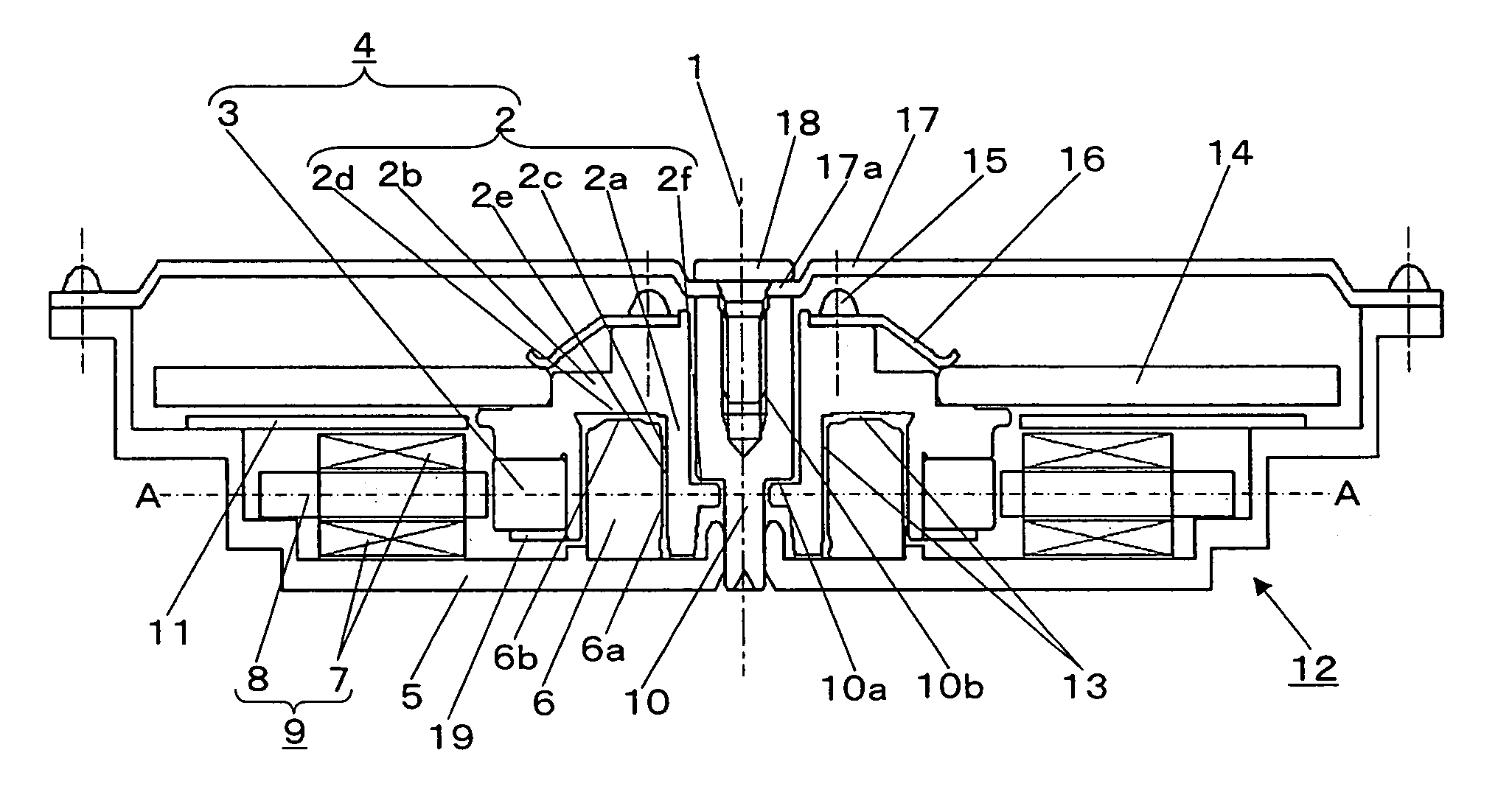
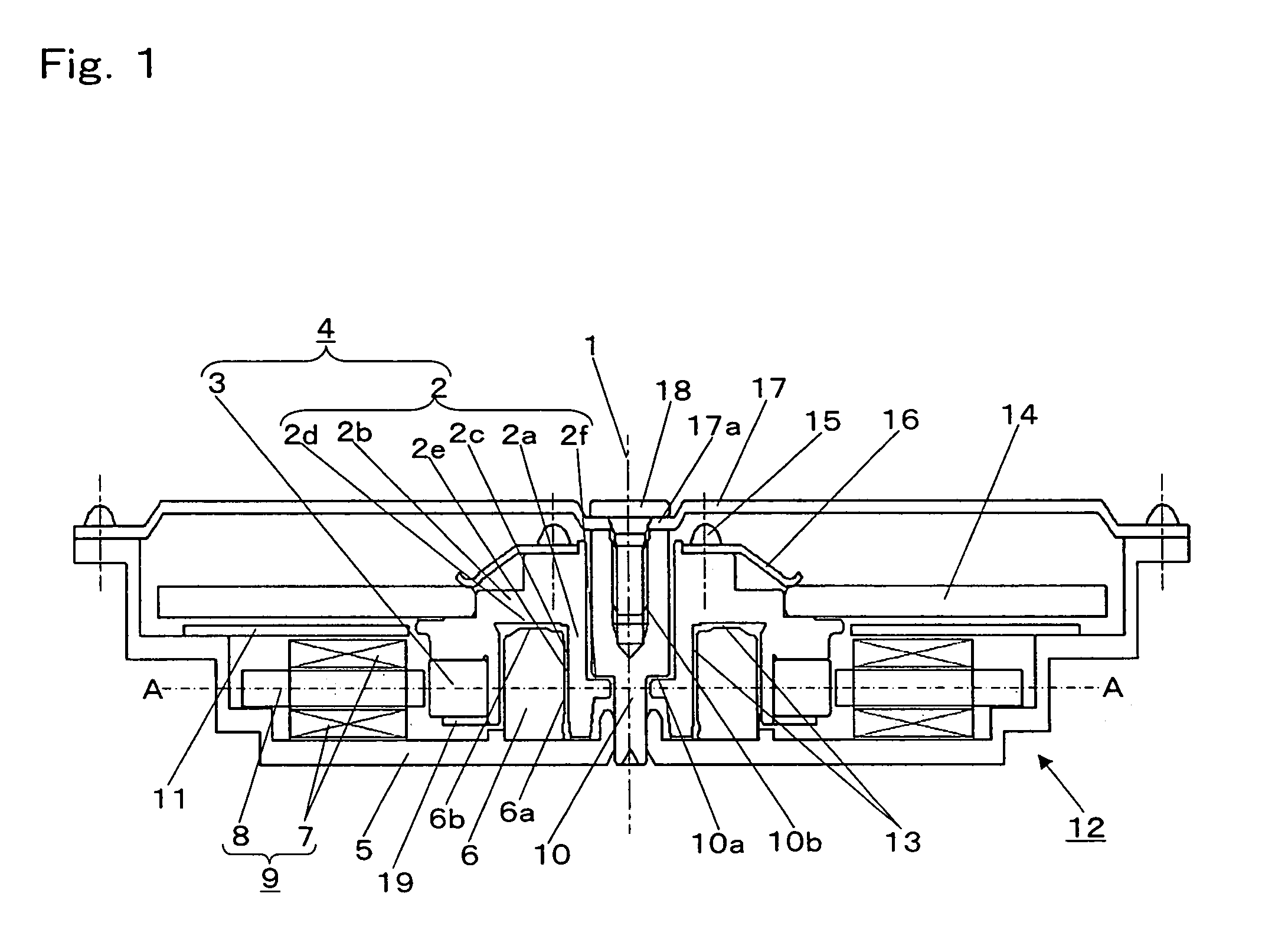
[0093]FIG. 1 and FIG. 2 describe a fluid bearing motor and a disk drive in the preferred embodiment 1 of the present invention.

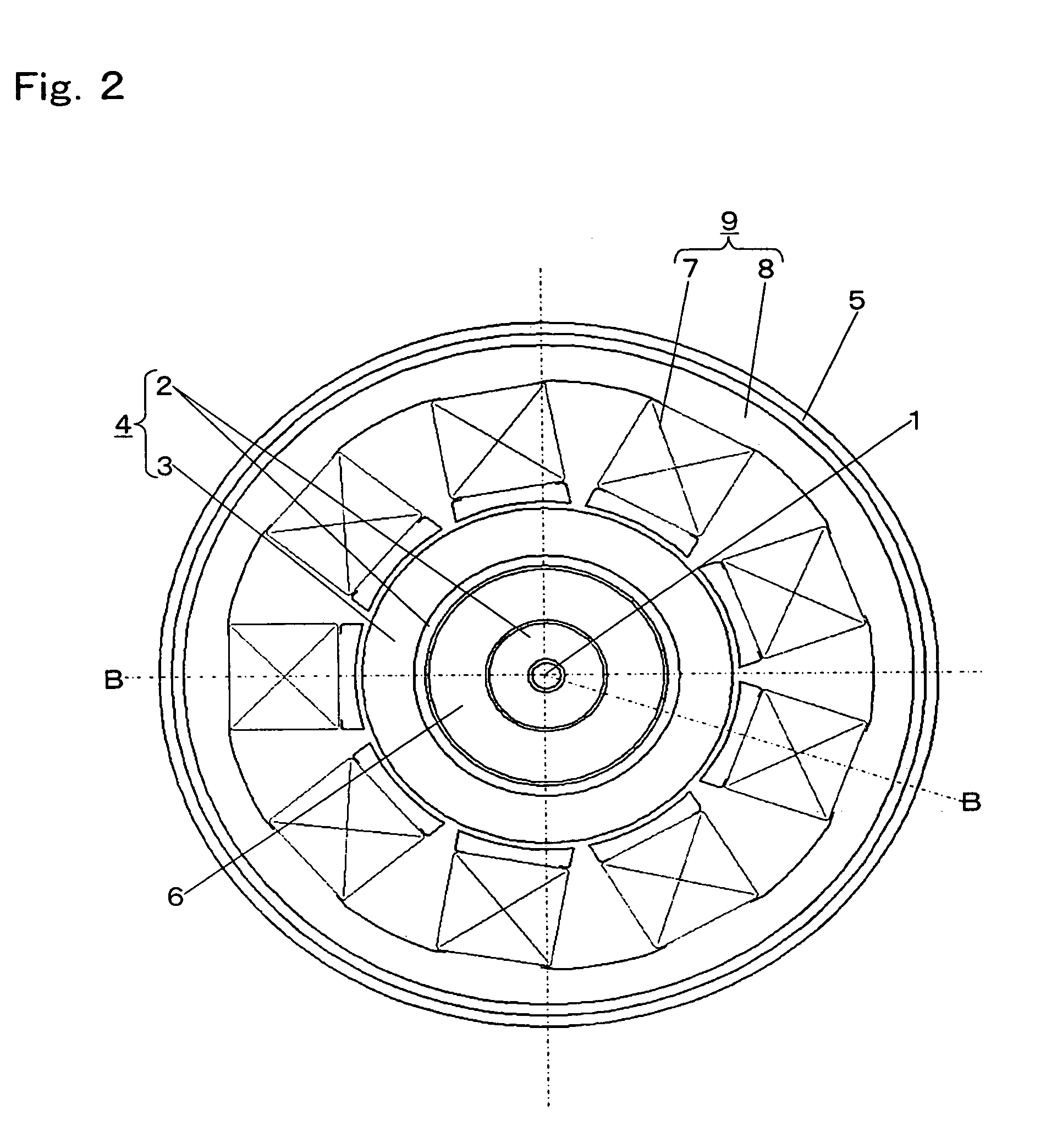
[0094]FIG. 1 is a side sectional view showing the configuration of main section of a fluid bearing motor of a disk drive in the preferred embodiment 1 of the present invention. FIG. 2 is a plane sectional view showing the configuration of main section of a fluid bearing motor of a disk drive in the preferred embodiment 1 of the present invention. FIG. 1 corresponds to the cross-section of the fluid bearing motor in the preferred embodiment 1 of the present invention when it is cut at the plane including the rotational center axis along the B—B line of FIG. 2. FIG. 2 corresponds to the cross-section of the fluid bearing motor in the preferred embodiment 1 of the present invention when it is cut along the A—A line of theFIG. 1.

[0095]In FIG. 1 and FIG. 2, rotor section 2 rotating around rotational center 1 includes hollow cylinder 2a and...

embodiment 2

(Preferred Embodiment 2)

[0122]FIG. 6 is a side sectional view showing the configuration of main section of a fluid bearing motor of a disk drive in the preferred embodiment 2 of the present invention. It shows the cross-section of the fluid bearing motor cut at a plane including the rotational center axis. In FIG. 6, same elements and names as in FIG. 1 are given same reference numerals.

[0123]In FIG. 6, the rotor section 2 rotating around the rotational center 1 includes the hollow cylinder 2a and flange 2b in the vicinity of rotational center 1. The outer periphery 2c of hollow cylinder 2a and the lower end 2d of flange 2b are formed with dynamic pressure generating grooves, and with rotary side bearing 2e that is a fluid bearing. The rotary magnet 3 magnetized by a plurality of magnetic poles is fixed on the underside of the outer periphery of flange 2b by means of press-fitting, bonding or other method. The rotary body 4 comprises the rotor section 2 and the rotary magnet 3.

[0124...

embodiment 3

(Preferred Embodiment 3)

[0136]FIG. 9 shows the configuration of main section of a fluid bearing motor of a disk drive in the preferred embodiment 3 of the present invention. The cross-section of the fluid bearing motor cut at a plane including the rotational center axis is shown in the figure. In FIG. 9, the same elements and names as in FIG. 1 and FIG. 6 are given same reference numerals.

[0137]In the present preferred embodiment, in place of projection 2g in the preferred embodiment 2, ring-form stop-ring 91 as a separate member is provided at the inner periphery of hollow cylinder 2a of rotor section 2, and projection 91b is formed.

[0138]Different points are mainly described in the following.

[0139]In FIG. 9, the inner periphery of hollow cylinder 2a of rotor section 2 configuring rotary body 4 is small in bore diameter at the flange 2b side, and large in bore diameter at the chassis 5 side. The third stepped surface 2j at the boundary between the small bore and the large bore is n...


PUM

PropertyMeasurementUnit
sizeaaaaaaaaaa
rotational forceaaaaaaaaaa
diameteraaaaaaaaaa

Abstract

The stop ring having a surface nearly vertical to the rotational center axis, which is projected at the inner periphery of the hollow cylinder of the rotor section, and the stepped surface of the fixed shaft secured on the chassis are opposed to each other with a predetermined slight clearance provided therebetween. The clearance is filled with magnetic fluid, and further, a permanent magnet is disposed on the chassis, opposing to the other surface of the stop ring.

Description

FIELD OF THE INVENTION[0001]The present invention relates to a fluid bearing motor used for a magnetic disk drive and an optical disk drive of a computer memory or a picture memory for recording / reproducing information at high densities, and a disk type recording / reproducing apparatus (hereinafter called disk drive) mounted with the same.BACKGROUND OF THE INVENTION[0002]Recently, in the field of information recording / reproducing apparatuses such as disk drive, efforts have been made to increase the capacity. For increasing the capacity, it is specially required to improve the rotational accuracy of the spindle motor for driving the disk used in the disk drive or the like. In order to meet the requirement for improving the rotational accuracy, there is an increasing trend of employing a hydrodynamic bearing in the spindle motor.[0003]In a hydrodynamic bearing, there exists a hydrodynamic lubricant between a rotary side bearing and a fixed side bearing. The rotary side bearing and the...

Claims


Application Information

Patent Timeline
Patent Type & Authority Patents(United States)
IPC IPC(8): H02K5/16F16C17/10F16C33/10G11B19/20H02K7/08
CPCF16C17/10F16C33/107H02K7/086G11B19/2009F16C2370/12
Inventor OBATA, SHIGEOMATSUOKA, KAORUKUWAJIMA, HIDEKIMIYAMORI, KENICHINODA, HIROMITSU
Owner PANASONIC CORP
Why Eureka
Try Eureka