Image synthesization method

Inactive Publication Date: 2006-08-01
CANON KK
View PDF24 Cites 88 Cited by
  • Summary
  • Abstract
  • Description
  • Claims
  • Application Information

AI Technical Summary

Benefits of technology

[0034]It is, therefore, one object of the present invention to provide an ima

Problems solved by technology

When an electronic camera is compared with a silver halide camera or a scanner, the low resolution (the small number of pixels) provided by the electronic camera is pointed out as a disadvantage.
In panoramic image synthesization, a process for erasing seams where segments overlap is important, and affects the quality of the resultant synthetic image.
The above described conventional technique has the following problems, however.
At this time, an error may occur at the synthesization position.
That is, since the minimum unit for which accuracy is possible when matching points are extracted is one pixel, and as accuracy can not be guaranteed if a unit that is smaller than one pixel is employed, an error occurs when a shift of less than one pixel occurs at the pixel synthesization position.
Again, however, for images, such as documents, that include characters, in many cases adverse effects are obtained, as has been previously described.
As for an electronic camera, it has been pointed out that low resolution (a small number of pixels) is one of their disadvantages when compared with silver halide cameras or scanners, as is described above.
For panoramic image synthesization, the most important process, and one that is difficult to accomplish, is finding a location where a plurality of images overlap.
The difficulty encountered in performing the matching point extraction process (the error rate) differs, depending on the images being processed.
However, when a

Method used


Image

  • Image synthesization method
  • Image synthesization method
  • Image synthesization method

Examples


first embodiment

[0170]the present invention will now be described in detail while referring to the accompanying drawings.

[0171]First, a first mode in the first embodiment of the present invention will be explained.

[0172]FIG. 4 is a schematic diagram illustrating the external appearance of a personal computer to which a panoramic image synthesizer of the first embodiment is applied.

[0173]As is shown in FIG. 4, the personal computer has a computer main body 301. A display 302 for displaying various data including image data concerning panoramic image synthesization; a mouse 303; a keyboard 305; and an electronic camera 307 are connected to the main body 301.

[0174]The mouse 303 is a representative pointing device, and has a mouse button 304.

[0175]The electronic camera 307 has an incorporated memory in which information concerning a photographic image is recorded, and is connected to the computer main body 301 by a general-purpose interface 306, such as a bidirectional parallel interface or an SCSI int...

second embodiment

[0339]the present invention will now be described while referring to the accompanying drawings.

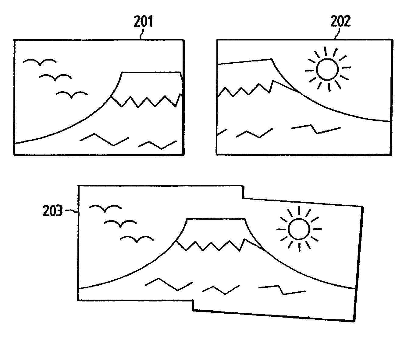
[0340]FIG. 41 is a block diagram illustrating a panoramic image synthesization system according to the second embodiment of the present invention. FIG. 42 is a diagram illustrating the external appearance of a personal computer system that serves as a platform on which the panoramic image synthesization system for this embodiment is carried out. In this embodiment, a plurality of images that are photographed by an electronic camera are synthesized by the personal computer to create a single panoramic image.

[0341]The personal computer system in FIG. 42 comprises: a computer system main body 1; a display device 2 for displaying data; a mouse 3 that is a representative pointing device and that has a mouse button 4; and a keyboard 5. In addition, an electronic camera 7 is connected to the computer system main body 1 via a general-purpose interface 6. The general-purpose interface 6 is a genera...

third embodiment

[0414]the present invention will now be described while referring to the accompanying drawings.

[0415]FIG. 55 is a block diagram illustrating a panoramic image synthesization system according to the third embodiment of the present invention. FIG. 56 is a diagram illustrating the external appearance of a personal computer system that serves as a platform on which the panoramic image synthesization system of this mode is carried out. In this embodiment, a plurality of images that are photographed by an electronic camera are synthesized by the personal computer to create a single panoramic image.

[0416]The personal computer system in FIG. 56 comprises: a computer system main body 1; a display device 2 for displaying data; a mouse 3 that is a representative pointing device and that has a mouse button 4; and a keyboard 5. In addition, an electronic camera 7 is connected to the computer system main body 1 via a general-purpose interface 6. The general-purpose interface 6 is a general-purpos...


PUM


Abstract

An image synthesization method, whereby a plurality of images, each of which has a partially overlapping image area, are synthesized to create a single synthetic image, comprises a determination step of inputting a plurality of image data sets that correspond to the plurality of images that are input, and of determining whether or not an image in the partially overlapping image area of each of images that are indicated by the plurality of image data sets includes mainly characters an image processing step of performing, for the plurality of image data sets that are input, image processing in consonance with a result of a determination performed at the determination step and an image synthesization step of synthesizing images that are indicated by the resultant plurality of image data, for which the image processing has been performed at the image processing step. With this arrangement, a plurality of images can be easily and effectively synthesized.

Description

[0001]This application is a divisional of application Ser. No. 08 / 719,716, filed on Sep. 25, 1996 now U.S. Pat. No. 6,549,681.BACKGROUND OF THE INVENTION[0002]1. Field of the Invention[0003]The present invention relates to an image synthesization method for synthesizing a plurality of images, in which the image areas partially overlap each other, in order to create a single synthetic image.[0004]2. Related Background Art[0005]The processing for the synthesization of a plurality of images that partially overlap each other, by using a computer to create a single synthetic image, is generally called panoramic image synthesization. This processing has been developed in response to a demand that it is possible to take a wide picture that constitutes a single image. When an electronic camera is compared with a silver halide camera or a scanner, the low resolution (the small number of pixels) provided by the electronic camera is pointed out as a disadvantage. For an image that is taken by ...

Claims


Application Information

Patent Timeline
IPC IPC(8): G06K9/32G06T3/40H04N1/387
CPCG06T3/4038H04N5/23238H04N1/3876H04N23/698
Inventor TAKIGUCHI, HIDEOYANO, KOTAROKATAYAMA, TATSUSHITAKAHASHI, FUMIAKIHATORI, KENJIHATANAKA, KOJI
Owner CANON KK
Why Eureka
Try Eureka