Control system for baling machine

a control system and baling machine technology, applied in the direction of program control, electric programme control, instruments, etc., can solve the problems of generating weaknesses or wear-points in baling wire, affecting the efficiency a certain degree of inefficiency of current automated baling machines, so as to efficiently control the knot knot tying, the effect of maximizing speed and precise torque control

Inactive Publication Date: 2006-08-01
L P BROWN COMPANY INC DELAWARE
View PDF61 Cites 21 Cited by
  • Summary
  • Abstract
  • Description
  • Claims
  • Application Information

AI Technical Summary

Benefits of technology

[0012]Control is effected through the PLC of the control system. Each axis of control, separately for each head, has a separate memory space in the control system of the present invention, so that each head may be controlled individually. The PLC and memory of the present control system track the precise position of the drive wheel shafts and Fastener head tying cylinder shafts at all times to within a thousandth of an inch. Thus, the control system can precisely measure and control position and speed. The amperage of current being used by the electro-servo motors controlling the drive wheels and tying cylinders is also precisely measured at all times. This current quantity corresponds to a quantity of torque which is pre-configured at optimal levels in the control systems memory. Precise torque control benefits wire tensioning and knot tying.
[0013]In operation, the position tracking of the present control system allows precise control of the speed of the progress of baling wire around the bulk material. In prior art balers the baling wire triggered a limit switch upon completion of its loop around the bulk material, which closed a rely, signaling a tensioning gripper to hold the end of the wire. In the present invention, precise electro servo tracking of wire payout replaces external limit switches. The drive wheels are then reversed in order to generate a pre-configured degree of tension on the baling wire.
[0014]This reverse tension is precisely controlled by the control system of the present invention through use of a pre-configured memory of the desired torque on the drive wheels. The torque is precisely monitored with constant servo motor feedback of the amperage drawn. Similarly, current feedback is monitored in the fastener electro-servo motor, which drives a rotational tying cylinder. Both torque control and position control are used by the control system of the present invention to efficiently control the tying of a knot in the baling wire in a fashion that maximizes speed while remaining within industry standard strength and tension limits. After looping the bale wire; releasing the wire from the wire guide track, tying the knot cutting the wire, the control system of the present invention is pre-configured to release the bale wire loops.

Problems solved by technology

Current automated baling machines operate with a certain degree of inefficiency.
Certain knotting speeds must be avoided because too much speed in the twisting procedure produces metal fatigue.
Too great a degree of tension overall can generate weaknesses or wear-points in the baling wire, or can generate wear in the wire guide tracks or other parts of the automated baling machine.
These wide margins of error manifest themselves in a variety of process difficulties, notably increased cycle time.
Moreover, wide margins of error necessitate use of heavier gauge wire, which is more expensive.

Method used


Image

  • Control system for baling machine
  • Control system for baling machine
  • Control system for baling machine

Examples


Embodiment Construction

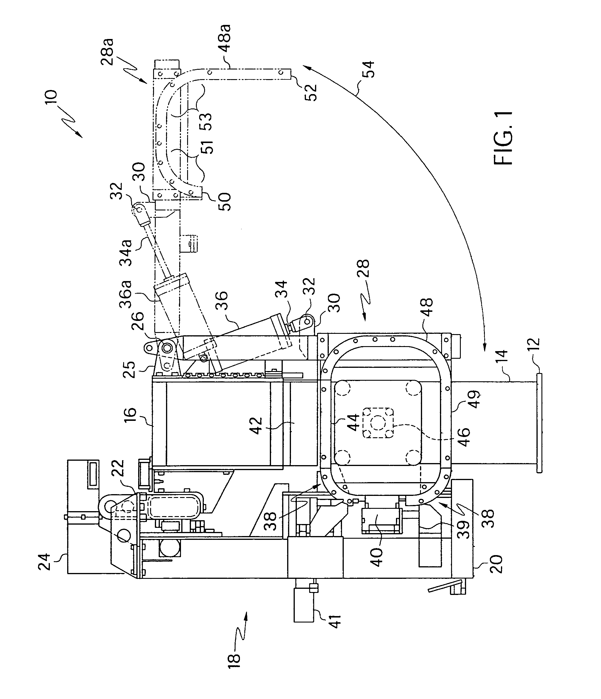
[0031]Referring to the accompanying drawings in which like reference numbers indicate like elements, FIG. 1 is a side view of an automatic baling machine. The bale binding apparatus, 10, is depicted to show two positions; the solid lines illustrate a first position wherein a moveable wire guide track section, 48, and moveable wire guide track section support strut assembly, 28, are in a first position to complete a wire guide track trajectory when bale binding is in progress; and the broken lines illustrate a second position wherein the moveable wire guide track section support strut assembly and moveable wire guide track section are removed to a second position, 28a. The second position allows ejection of the finished, bound bale. A third “ready” position (not shown) is between the two illustrated positions. In the “ready” position, the wire guide tracks are clear of the vertical path of the bale compressor apparatus, but not high enough to be clear of a horizontal ejection path.

[0...


PUM


Abstract

A control system for a bulk material baler embodied in a machine readable data structure and including an instruction to a moveable guide track to move from a removed position to a closed position to create a guide track loop around a volume of bulk material to be baled while that bulk material is under compression and also including in instruction to a bale strap feed drive to feed a pre-determined length of strapping around the guide track loop, and including an instruction to a cutter to cut the end of the bale strap and including an instruction to a strap fastener to fasten together the ends of the bale strap and including an instruction to remove the moveable guide track section from around the bale and an instruction to release compression and an instruction to eject a bound bale.

Description

CROSS-REFERENCE TO RELATED APPLICATIONS[0001]This application is a continuation of U.S. application Ser. No. 09 / 919,111 filed Jul. 31, 2001, now U.S. Pat. No. 6,633,798.STATEMENT REGARDING FEDERALLY SPONSORED RESEARCH OR DEVELOPMENT[0002]Not Applicable.BACKGROUND OF THE INVENTION[0003]1. Field of the Invention[0004]This invention relates generally to a wire bale binding machine that uses a control system incorporating memory, sensors and programmable logic controllers.[0005]2. Related Art[0006]Wire baling of bulk materials benefits from increased speed and reduced materials cost through automation. Bulk materials include fibrous bulk materials such as cotton and nylon. Fibrous materials are commonly formed into bales by simultaneous compression and binding. There is a continuing need in the automated baling art to improve the efficiency, reliability and accuracy of the bale binding process.[0007]Baling wire performance requirements vary depending upon the bulk material being baled. ...

Claims


Application Information

Patent Timeline
Patent Type & Authority Patents(United States)
IPC IPC(8): G01M1/38B65B13/02G05B13/00G06F19/00B30B9/30B65B27/12B65B57/00
CPCB30B9/3007B65B57/00B65B27/12
Inventor TIMOTHY, STAMPSDANIEL, BARTPHILLIPS, STEVENDUTTON, JAMES
Owner L P BROWN COMPANY INC DELAWARE
Why Eureka
Try Eureka