Cooling apparatus for fuel cell utilizing air conditioning system

a fuel cell and cooling apparatus technology, applied in the field of fuel cells, can solve problems such as the heating system, and achieve the effect of effective fuel cell membrane electrode assembly

Inactive Publication Date: 2006-08-08
DENSO CORP
View PDF18 Cites 11 Cited by
  • Summary
  • Abstract
  • Description
  • Claims
  • Application Information

AI Technical Summary

Benefits of technology

[0011]Another object of the present invention is to provide a cooling apparatus for a fuel cell capable of reducing power used for a re-start, and the size of an external heat exchanger of a heat pump, by the application of the heat pump (cooling apparatus) and a heat storage unit.
[0013]By configuring as described above, the radiator becoming bulky in order to provide the large cooling capacity for cooling the fuel cell is replaced with a refrigerating cycle system and, therefore, the cooling apparatus for a fuel cell can be made compact. Further, it is possible to warm up the fuel cell, cooled to a low temperature while it is left in a stopped state, and to improve the efficiency of the fuel cell itself by reducing the time required for starting and increasing the efficiency of warming-up.
[0020]According to the present aspect, it is possible to make the membrane electrode assembly of the fuel cell work effectively.

Problems solved by technology

As described above, there are various problems regarding a conventional warming-up system for a fuel cell.

Method used


Image

  • Cooling apparatus for fuel cell utilizing air conditioning system
  • Cooling apparatus for fuel cell utilizing air conditioning system
  • Cooling apparatus for fuel cell utilizing air conditioning system

Examples


first embodiment

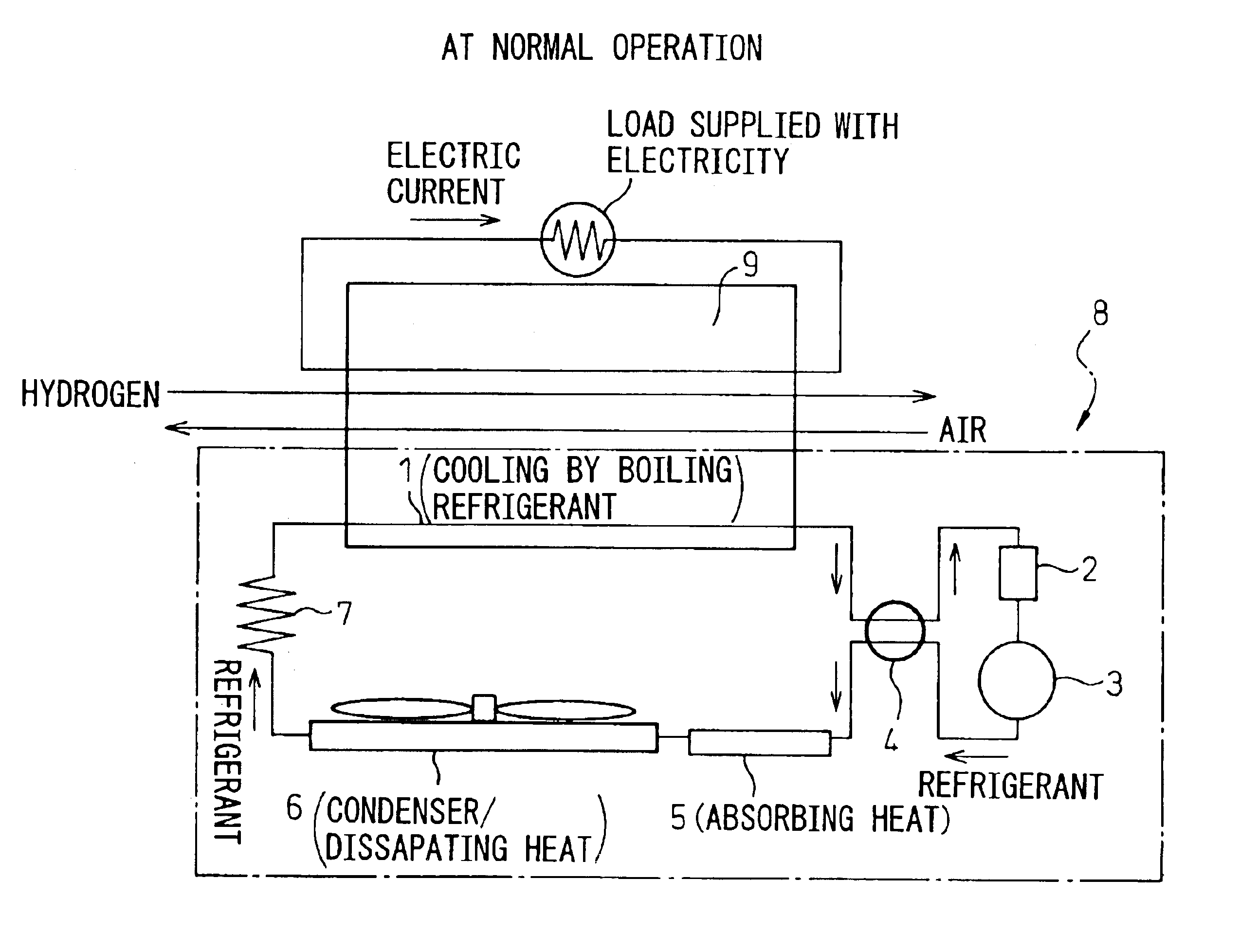
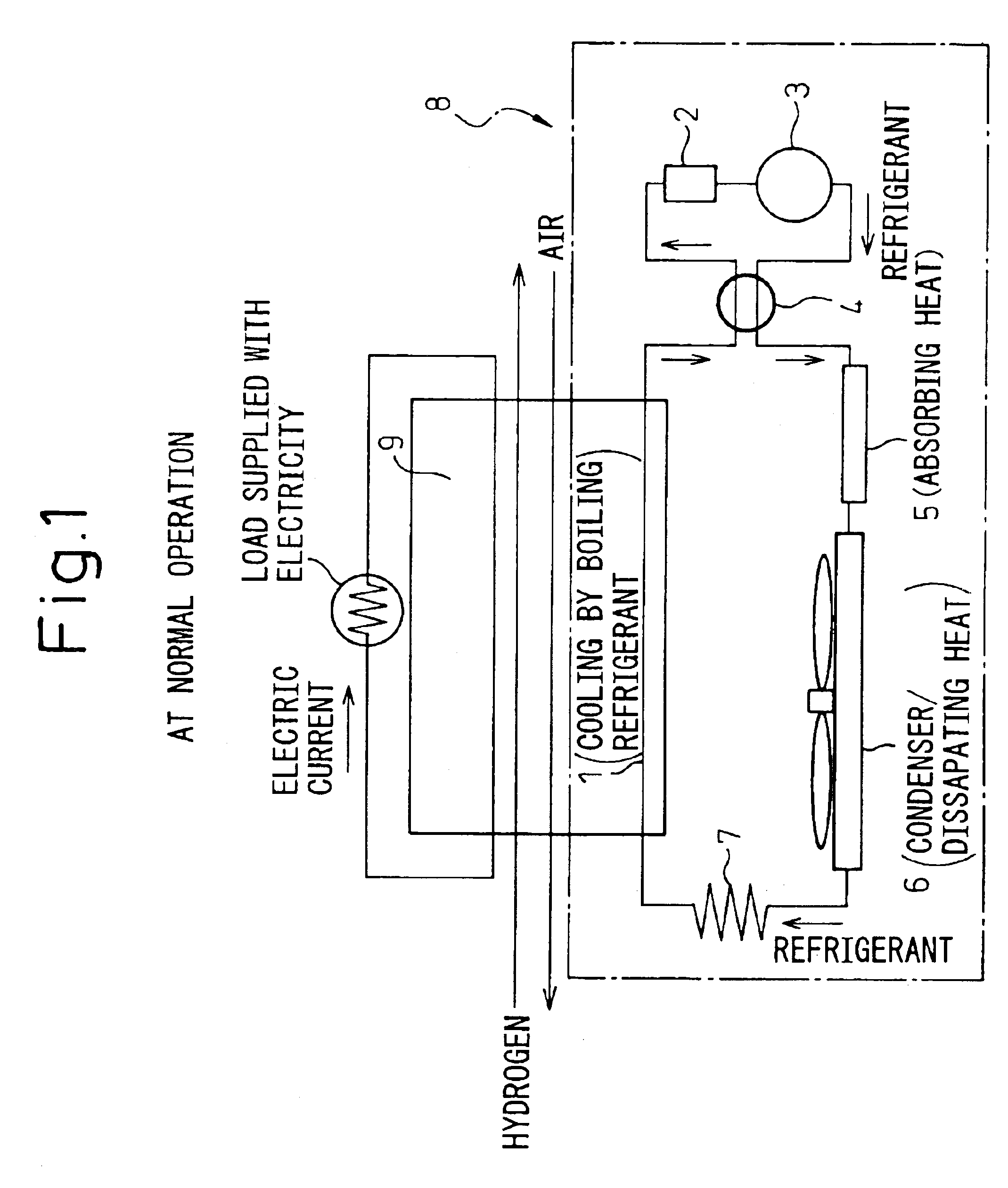
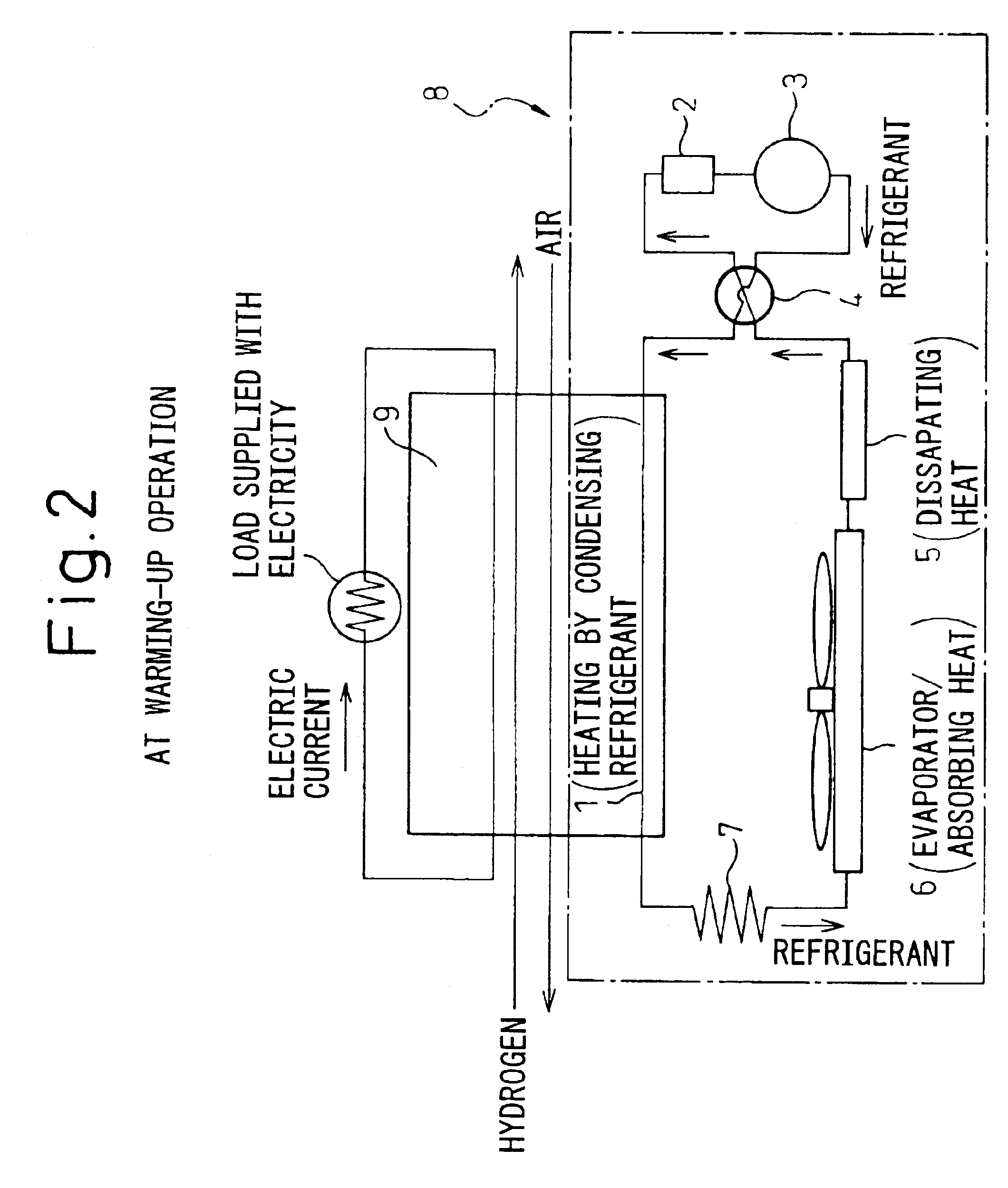
[0041]FIG. 1 and FIG. 2 schematically show a cooling apparatus for a fuel cell according to the present invention: FIG. 1 shows a general configuration of the cooling apparatus of the present invention and an outline during a normal operation of the fuel cell (during a cooling operation); and FIG. 2 shows an outline of the cooling apparatus of the present invention during a warming-up operation of the fuel cell.

[0042]In FIG. 1, a cooling apparatus 8 in the present embodiment is connected to a stack main body 9 of a fuel cell for a vehicle, and the operation state during the cooling operation, that is, during the normal operation, is shown schematically. The cooling apparatus 8 comprises a cooling circuit and the cooling circuit in the present embodiment has a compressor 3 for compressing gaseous refrigerant, a heat storage unit 5 for storing heat by absorbing the heat of the refrigerant during the normal operation, an external heat exchanger 6 functioning as a condenser during the n...

second embodiment

[0061]the present invention according to the first embodiment described above, in which the heat of the heat storage unit 5 is supplied for warming-up to another components, such as a hydrogen supply system of the fuel cell system, is shown in FIG. 5. The same reference symbols are assigned to the components in FIG. 5, which are the same as or similar to those in the first embodiment disclosed in FIG. 1.

[0062]In the second embodiment in FIG. 5, in addition to the first embodiment, a branch line 13 and a branch valve 12, such as an electromagnetic valve, are provided between the heat storage unit 5 and the four-way valve 4, the refrigerant is supplied to another device 11 through the branch line 13, and the device 11, which is a component included in the fuel cell system is further warmed up, during the warming-up operation, by the use of the heat stored in the heat storage unit 5 during the normal operation. The device 11, may be, for example, at least a component of the hydrogen su...

third embodiment

[0065]the present invention according to the first embodiment is a configuration of dual system, in which the cooling apparatus 8 capable of carrying out the refrigerating cycle is also used for an air conditioning system for a vehicle compartment and the cooling apparatus 8, which is a heat pump, and the air conditioning system for a vehicle compartment are operated by the compressor 3 alone, is shown in FIG. 6. The same reference symbols are assigned to the components in FIG. 6, which are the same as or similar to those in the first embodiment disclosed in FIG. 1.

[0066]In the third embodiment in FIG. 6, in addition to the first embodiment, a branch line 23 and a branch valve 22, such as an electromagnetic valve, are provided between the pressure-reducing means 7 and the stack main body 9, the refrigerant is supplied to an air conditioning system 21 through the branch line 23 and, during the normal (cooling) operation, the fuel cell stack main body 9 is cooled and, at the same time...


PUM

PropertyMeasurementUnit
temperatureaaaaaaaaaa

Abstract

A cooling circuit of a cooling apparatus for a fuel cell comprises a compressor for compressing a gaseous refrigerant, an external heat exchanger arranged on the downstream side of the compressor and for liquefying the compressed refrigerant, a pressure-reducing means arranged on the downstream side of the external heat exchanger, and an accumulator for storing the refrigerant which cools a fuel cell stack main body. The stack main body is connected to the cooling circuit between the pressure-reducing means and the accumulator and a four-way valve is arranged between the compressor and the external heat exchanger, and between the stack main body and the accumulator in the cooling circuit, and the four-way valve introduces the refrigerant from the compressor to the external heat exchanger during the cooling operation, and introduces it to the stack main body during the warming-up operation.

Description

BACKGROUND OF THE INVENTION[0001]1. Field of the Invention[0002]The present invention relates to a fuel cell. Particularly, the present invention relates to a fuel cell mounted on a vehicle or, more particularly, a cooling apparatus capable of warming up the fuel cell.[0003]2. Description of the Related Art[0004]In recent years, a fuel cell has attracted interest from the standpoint of its eco-friendliness, high efficiency and the like, and is under development as an energy source for vehicles. In a vehicle, when the fuel cell is used as its drive source, it is necessary to quickly warm up the fuel cell itself up to predetermined proper operating temperatures when starting a vehicle from a stopped state.[0005]As a warming-up system of a fuel cell for a vehicle, a system for warming cooling water of the fuel cell by the use of a heater (for example, see Patent document 1) has been proposed in the prior art. This warming-up system of a fuel cell is an excellent system with high effici...

Claims


Application Information

Patent Timeline
Patent Type & Authority Patents(United States)
IPC IPC(8): F25B27/00H01M8/04
CPCH01M8/04014Y02E60/50H01M8/04029
Inventor YOSHII, KEIICHITAKEDA, YUKIHIKO
Owner DENSO CORP
Why Eureka
Try Eureka