
Hydraulic governor device for use with a rotational shaft, and door assembly including the same

Inactive Publication Date: 2006-08-08
CANIMEX
View PDF10 Cites 12 Cited by
  • Summary
  • Abstract
  • Description
  • Claims
  • Application Information

AI Technical Summary

Benefits of technology

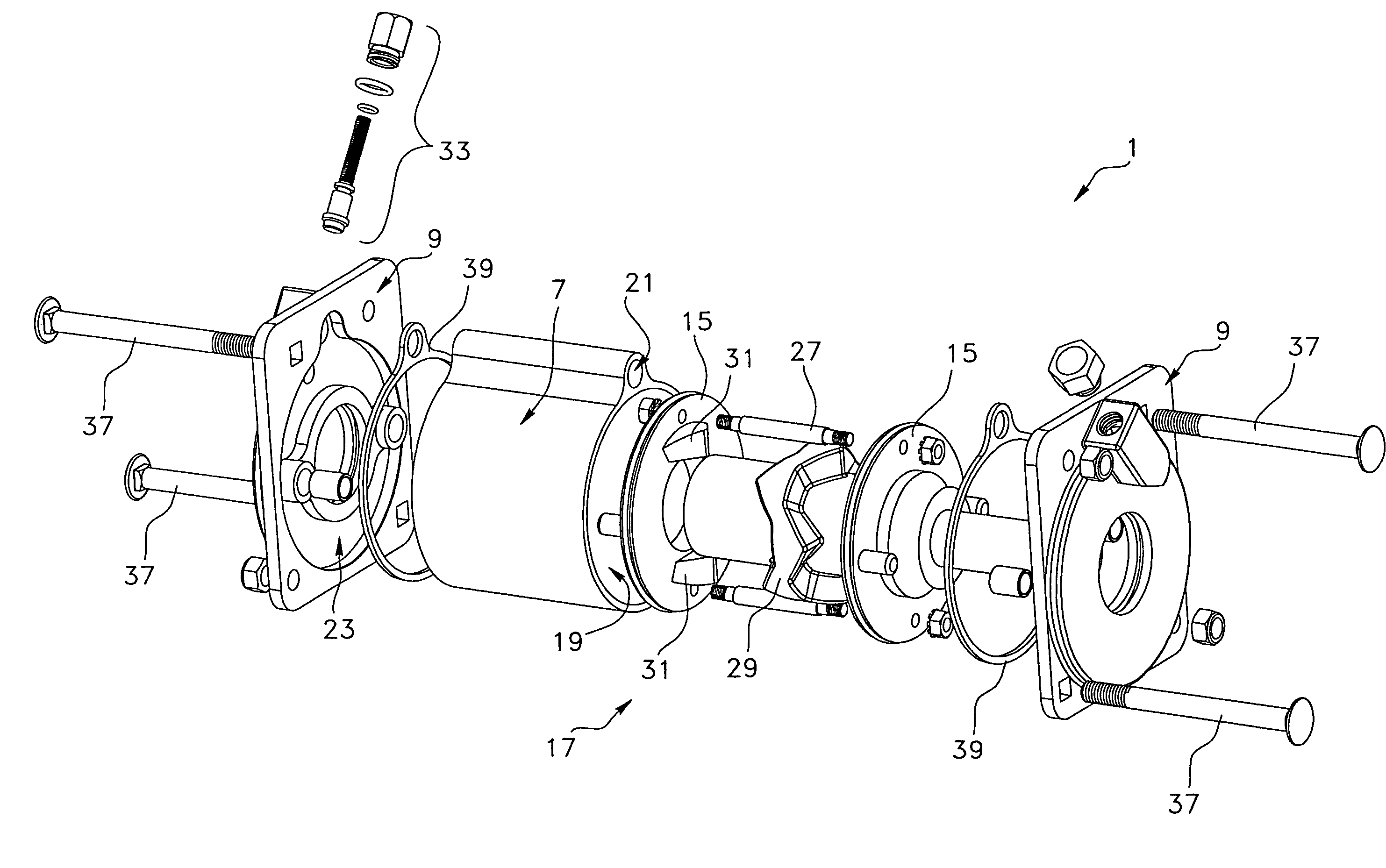
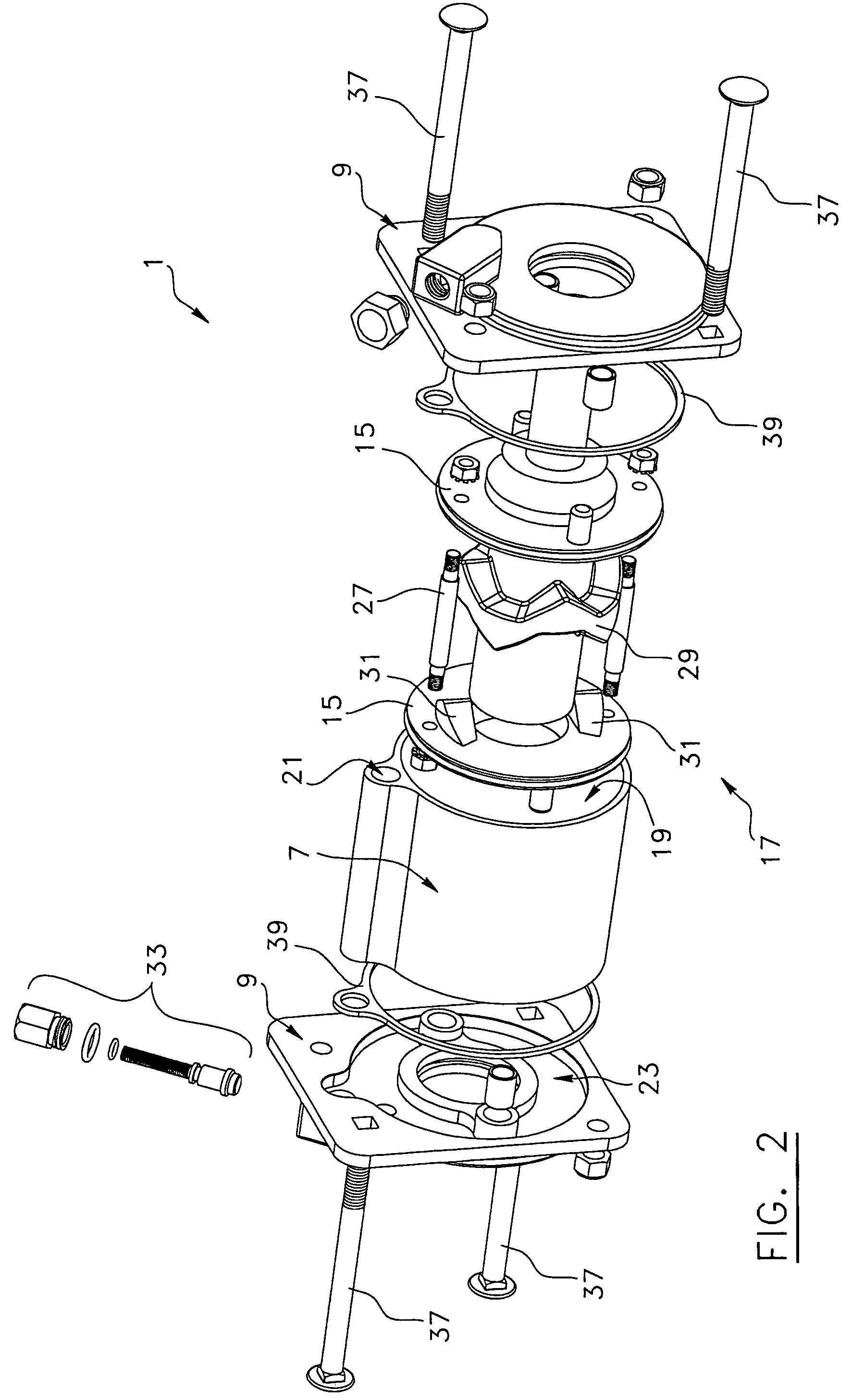
[0017]a reciprocating assembly operatively connected between the input shaft and the piston disks and cooperating with the same for converting a rotation of the input shaft into a reciprocating movement of the pistons disks within the chamber, so that said reciprocating movement of the pistons disks inside the chamber causes in turn the fluid to travel along a reciprocating movement along the hydraulic flow path, said reciprocating movement of the fluid along the hydraulic flow path causing a damping effect of the rotation of the input shaft and thus controlling the rotation of the rotational shaft of the door assembly via a damping effect.
[0025]a reciprocating assembly operatively connected between the input shaft and the piston disks and cooperating with the same for converting a rotation of the input shaft into a reciprocating movement of the pistons disks within the chamber, so that said reciprocating movement of the pistons disks inside the chamber causes in turn the fluid to travel along a reciprocating movement along the hydraulic flow path, said reciprocating movement of the fluid along the hydraulic flow path causing a damping effect of the rotation of the input shaft and thus controlling the rotation of the rotational shaft of the door assembly via a damping effect.

Problems solved by technology

These problems occur when there is a need to control the speed of the weight which is deprived of a driving (or “counterbalancing”) mechanism.
Generally, such a situation occurs when the driving mechanism is not designed to control the speed in both directions or when there is an emergency situation or failure of the mechanism.
Sometimes, driving mechanisms are not totally fail safe by design.
Very often, such a behavior is not acceptable for many devices and mechanisms because a weight several feet above ground is still subject to fall if the link of the device or mechanism fails, and, if it is the case, there is nothing to stop or control the falling of the weight.
A problem associated with this type of viscous damper is the fact that it is not adjustable in real-time and it is not autonomous or disc-brake controlled by an electronic device with a feedback system to produce a governor-like behavior.
Furthermore, another problem associated with this type of viscous damper is the fact that it requires an external source of power and is more complex than other governor devices.
Also known in the art are the many problems associated with these types of devices, which are related to the design of any governing mechanism, that is intended to be totally fail safe, examples of which are the following: the limited space available to implement the governing device; the need of feedback mechanisms to adjust the speed rate; the constant torque given by the braking device; the lack of mechanism that gives high torque in function of the speed rate; the lack of easy and real-time adjustment in the governing device; and the relative high cost of such devices.
Hence, a big challenge essentially lies is resolving these different aspects with a single integrated system.

Method used


Image

  • Hydraulic governor device for use with a rotational shaft, and door assembly including the same
  • Hydraulic governor device for use with a rotational shaft, and door assembly including the same
  • Hydraulic governor device for use with a rotational shaft, and door assembly including the same

Examples


Embodiment Construction

[0033]In the following description, the same numerical references refer to similar elements. The embodiments shown in the figures are preferred.

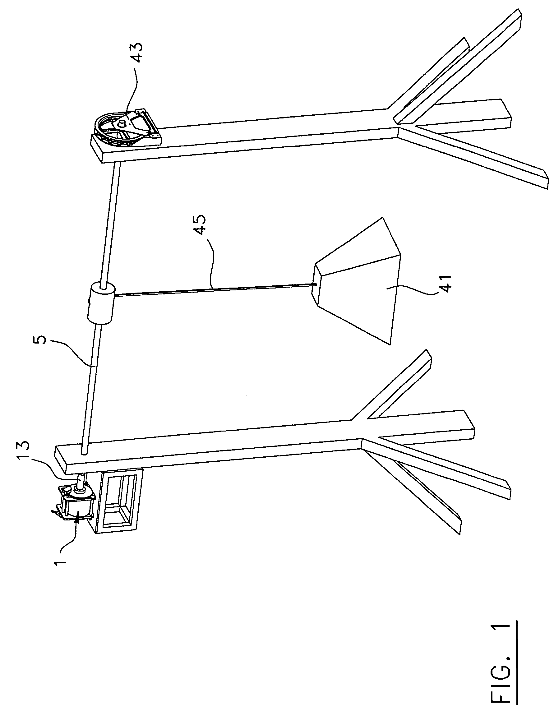
[0034]Moreover, although the present invention was primarily designed for use with rotational shafts (or “overhead shafts”) of garage door assemblies and the like, it may be used with other rotational shafts and in other fields, as apparent to a person skilled in the art. For this reason, expressions such as “garage”, “overhead”, “shaft”, etc., used herein should not be taken as to limit the scope of the present invention and includes all other kinds of doors or items with which the present invention could be used and may be useful. As will also be easily understood, the cross-sectional area of the shaft according to the present invention is not necessarily limited to a circular configuration, and may take on other suitable geometrical configurations, such a square, rectangular, triangular, etc., as also apparent to a person skilled in the a...


PUM


Abstract

A hydraulic governor device for use with a rotational shaft of a door assembly for controlling a rotation of said rotational shaft. The device includes a sleeve; first and second end coverings mounted respectively onto first and second ends of the sleeve so as to define an hydraulic flow path; a fluid substantially filling the hydraulic flow path; an input shaft extending through the ends coverings and the chamber, and being operatively connected to the rotational shaft of the door assembly; first and second pistons disks positioned inside the chamber and mounted about the input shaft, the pistons disks being connected to each other and being slidably movable along the input shaft; and a reciprocating assembly operatively connected between the input shaft and the piston disks and cooperating with the same for converting a rotation of the input shaft into a reciprocating movement of the pistons disks within a chamber, so that said reciprocating movement of the pistons disks inside the chamber causes in turn the fluid to travel along a reciprocating movement along the hydraulic flow path, said reciprocating movement of the fluid along the hydraulic flow path causing a damping effect of the rotation of the input shaft and thus controlling the rotation of the rotational shaft of the door assembly via a damping effect.

Description

FIELD OF THE INVENTION[0001]The present invention relates to a governor device. More particularly, the present invention relates to a hydraulic governor device for use with a rotational shaft, such as the overhead shaft of garage doors, mini-warehouse doors, commercial rolling steel doors and the like, for instance, the device being used to controllably govern the rotation of the shaft operatively actuated by a torque resulting from a given force. For example, the device may be used to controllably govern the rotation of an overhead shaft of a garage door operatively connected to a driving mechanism or a counterbalancing mechanism in the event of a failure and / or undesirable effect of said mechanism so as to prevent the garage door from falling uncontrollably to the ground due to the weight of the door or move up uncontrollably due to an excessive upward counterbalancing force.BACKGROUND OF THE INVENTION[0002]It is known in the art that several engineering problems are related in on...

Claims


Application Information

Patent Timeline
IPC IPC(8): E05F15/20E05D13/00E05F15/50F16F9/12F16F9/19
CPCE05D13/003E05D13/12E06B9/84F16F9/19E05D13/1215E05D13/1261F16F2232/04E06B2009/808E05Y2900/106E05Y2900/00
Inventor BARRIAULT, PATRICKBEAUDOIN, FRANCOISROY, DANNY
Owner CANIMEX
Learn More