Vane pump having an abradable coating on the rotor

a technology of rotor and rotor, which is applied in the direction of rotary/oscillating piston pump components, machines/engines, liquid fuel engines, etc., can solve the problems of reducing the volumetric efficiency of the vane pump and the loss of so as to reduce the effective operating clearance, reduce the effect of manufacturing tolerances, and increase the volumetric efficiency of the pump

Inactive Publication Date: 2006-08-08
GM GLOBAL TECH OPERATIONS LLC +1
View PDF21 Cites 0 Cited by
  • Summary
  • Abstract
  • Description
  • Claims
  • Application Information

AI Technical Summary

Benefits of technology

[0005]One advantage of the present invention is that the abradable coating material applied to the rotor has the beneficial effect of reducing the effective operating clearance between the surfaces of the rotor and the adjacent surfaces of the thrust and pressure plates and cam ring. The coating material is applied to the rotor and, during initial operation, any excess attributed to high spots is abraded away, producing the least amount of clearance necessary between the rotor and the adjacent plates and cam ring needed to operate the pump, and consequently increasing the volumetric efficiency of the pump.
[0006]The invention has the further advantage of minimizing the effects of manufacturing tolerances from pump to pump. With application of the abradable coating to the rotor, the coating which effectively fills the excess gap that would otherwise be present due to tolerance differences. As such, whatever variations are present in any given vane pump, the abradable coating compensates by reducing clearances where necessary and abrading away in areas where the full thickness of the coating is not needed in order to provide each pump with the optimum minimum operating clearance for maximum volumetric efficiency.
[0007]The invention has the further advantage of enabling the abradable coating to be applied to one component, namely the rotor, and having the effect of reducing the effective operating clearance between several components, namely the rotor, thrust plate, pressure plate and cam ring. However, the coating could be applied to one or more of the other components as well.

Problems solved by technology

Fluid leakage from the pump chamber is attributable to the extra clearance for flexure of the pressure plate reduces the volumetric efficiency of the vane pump.
Even without such flexure, the presence of the operating clearance lends to a loss of volumetric efficiency of the pump due to fluid leakage.

Method used


Image

  • Vane pump having an abradable coating on the rotor
  • Vane pump having an abradable coating on the rotor
  • Vane pump having an abradable coating on the rotor

Examples


Embodiment Construction

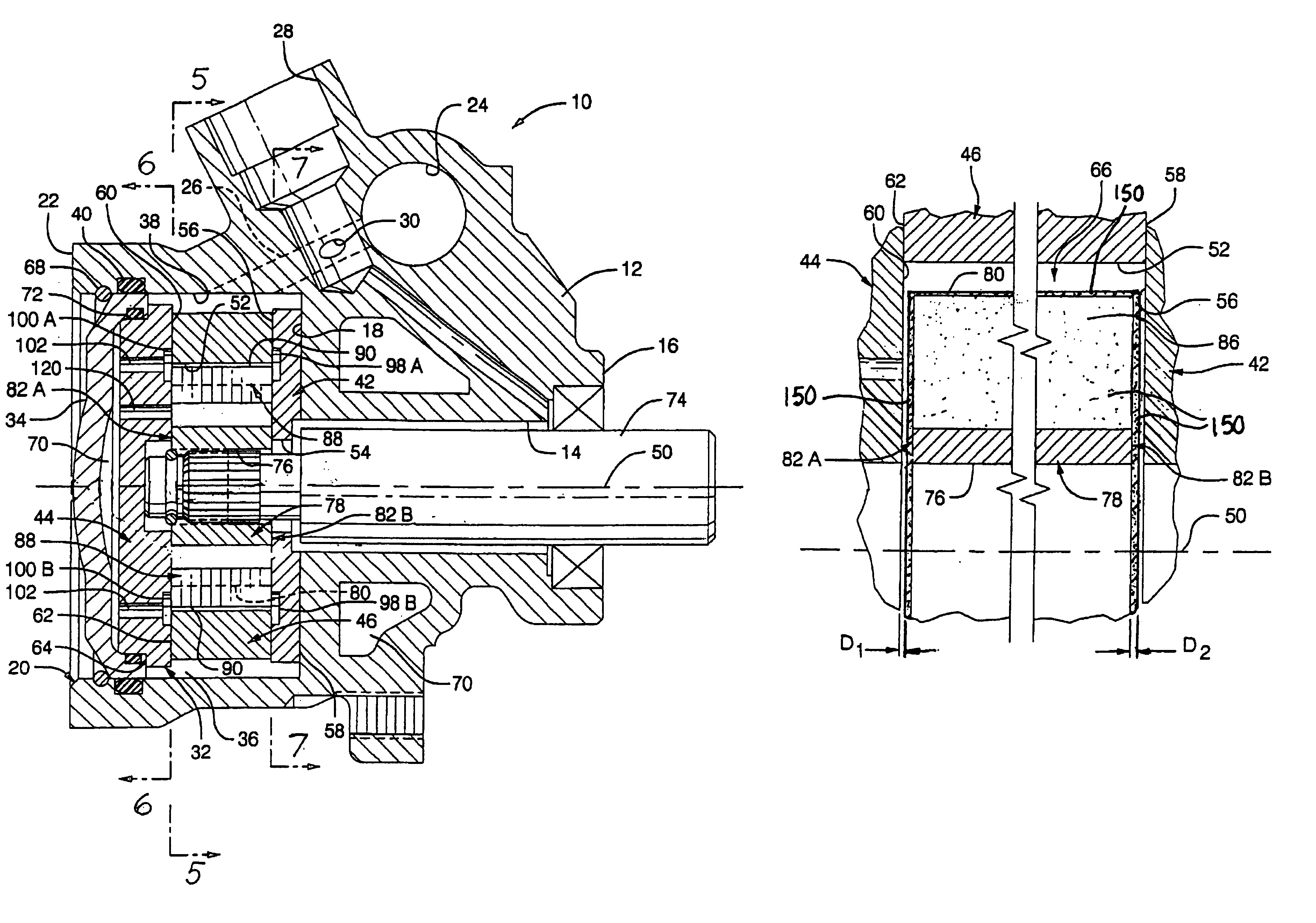
[0016]A vane pump constructed according to a presently preferred embodiment of the invention is shown generally at 10 in the drawings and includes a housing 12 having a drive shaft bore 14 open through a first end 16 and intersecting a flat bottom 18 of a large counter bore 20 in a second end 22 of the housing. A control valve bore 24 in the housing 12 communicates with the counter bore 20 through a schematically represented internal passage 26 in the housing. An inlet passage 28 in the housing communicates with a reservoir of fluid (not shown) and with the internal passage 26 through an aperture 30.

[0017]A “rotating group”32 of the vane pump 10 is captured in the counter bore 20 between the flat bottom 18 and a disc-shaped cover 34, closing the open end of the counter bore. An annular chamber 36 is defined between a cylindrical side wall 38 of the counter bore 20 and the rotating group 32. A seal ring 40 suppresses fluid leakage between the housing 12 and the cover 34. The rotating...


PUM


Abstract

A vane pump includes a cylindrical rotor rotatable inside of an oval-shaped rotor chamber of cam ring disposed between a pressed plate and a pressure plate. The rotor has opposite sides and a peripheral outer surface in which radial vane slots are formed and guide slideable vanes. The rotor is coated on its surfaces with a film of abradable coating material which reduces the operating clearance between the rotor and the thrust and pressure plates and cam ring so as to increase the volumetric efficiency of the pump.

Description

TECHNICAL FIELD[0001]This invention relates to vane pumps.BACKGROUND OF THE INVENTION[0002]A vane pump typically includes a cylindrical rotor rotatable inside of an oval-shaped rotor chamber defined by a cam ring around the rotor. The cam ring and the rotor define a crescent-shaped cavity therebetween which is divided into a plurality of pump chambers by a corresponding plurality of flat vanes in radial vane slots in the rotor. The pump chambers expand in an inlet sector of the crescent-shaped cavity and collapse in a discharge sector of the crescent-shaped cavity as the rotor rotates. A thrust plate and a pressure plate on opposite sides of the cam ring cover the rotor chamber and are squeezed together by a plurality of hold-down springs or the like. Fluid in a discharge chamber of the vane pump and a discharge pressure reacts against the pressure plate to further clamp the cam ring between the pressure plate and the thrust plate. A significant fluid pressure differential across th...

Claims


Application Information

Patent Timeline
Patent Type & Authority Patents(United States)
IPC IPC(8): F04C2/344F01C19/00F01C21/08
CPCF01C19/005F01C21/08F04C2/3446F04C2230/91F04C2230/602
Inventor WONG, ALBERT CHEUK-YINWONG, TOM CHEUK-IN
Owner GM GLOBAL TECH OPERATIONS LLC
Why Eureka
Try Eureka