Radiation three-dimensional position detector

a detector and three-dimensional technology, applied in the direction of instruments, radiation measurement, measurement devices, etc., can solve the problems of limiting the number of scintillator arrays to be laminated, limiting the detection accuracy of the position of absorbed radiation, and difficult to determine the corresponding scintillator cells

Active Publication Date: 2006-08-08
HAMAMATSU PHOTONICS KK
View PDF11 Cites 15 Cited by
  • Summary
  • Abstract
  • Description
  • Claims
  • Application Information

AI Technical Summary

Benefits of technology

[0017]It is preferred that in each of the K layers scintillator arrays, in the radiation three-dimensional position detector in accordance with the present invention, a medium between two neighboring scintillators is made up of either of a reflective material or a translucent material with respect to the scintillation light, wherein preferably an area covered with the reflective material in the k1-the layer scintillator array and an area covered with the reflective material in the k2-th layer scintillator array appear different from each other on being viewed in the lamination direction of the layers. Further, it is preferred that, in the radiation three-dimensional position detector in accordance with the present invention, (1) in a scintillator array of the k1-th layer, a medium between a scintillator cell Ck1,p,n and a scintillator cell Ck1,p+1,n, and a medium between a scintillator cell Ck1,m,q and a scintillator cell Ck1,m,q+1 are made up of a reflective material respectively with respect to the scintillation light, whereas a medium between other scintillator cells is made up of a translucent material with respect to the scintillation light, (2) in a scintillator array of the k2-th layer, a medium between a scintillator cell Ck2,r,n and a scintillator cell Ck2,r+1,n, and a medium between a scintillator cell Ck2,m,s and a scintillator cell Ck2,m,s+1 are made up of a reflective material respectively with respect to the scintillation light, whereas medium between other scintillator cells is made up of a translucent material with respect to the scintillation light, and (3) “r” and “s” are an integer number respectively in a arithmetic progression with a tolerance of 2; 1≦p<M, 1≦q<N, 1≦r<M, 1≦s<N, “p≠r” or “q≠s”. In these cases, the position of barycenter of the scintillation light incidence on the light incident plane in the light receiving element corresponds to the scintillation light generation point (i.e., position of the absorbed radiation), furthermore, the range of the intensity distribution of the scintillation light in the light incident plane of the light receiving element is satisfactorily narrow, thus, the position of the barycenter of each light incidence is satisfactorily recognizable.

Problems solved by technology

If the intensity distribution of the scintillation light has a wide range in the light incident plane of the light receiving element, it is difficult to determine the corresponding scintillator cell based on the position of the barycenter.
Accordingly, there is a limit to any increase in the number of scintillator arrays to be laminated in built-up layers, and also, there is a limit in regard to detection accuracy of the position of the absorbed radiation.
Accordingly, in this case also, there is a limit to any increase in the number of laminated scintillator arrays, and also, there is a limit in regard to detection accuracy of the position of the radiation absorption.

Method used


Image

  • Radiation three-dimensional position detector
  • Radiation three-dimensional position detector
  • Radiation three-dimensional position detector

Examples


first embodiment

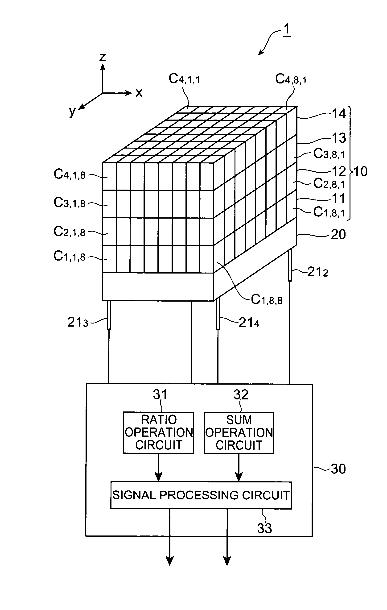
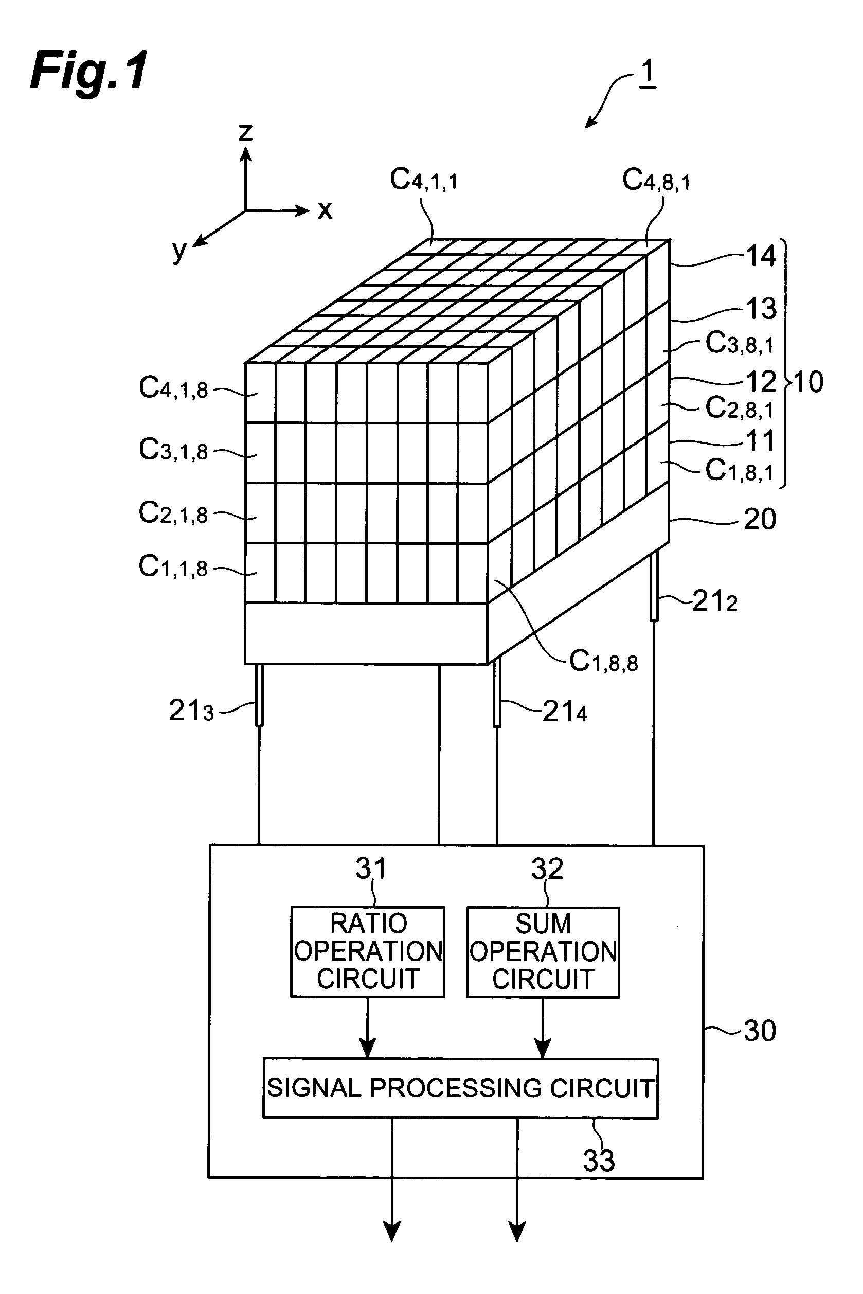
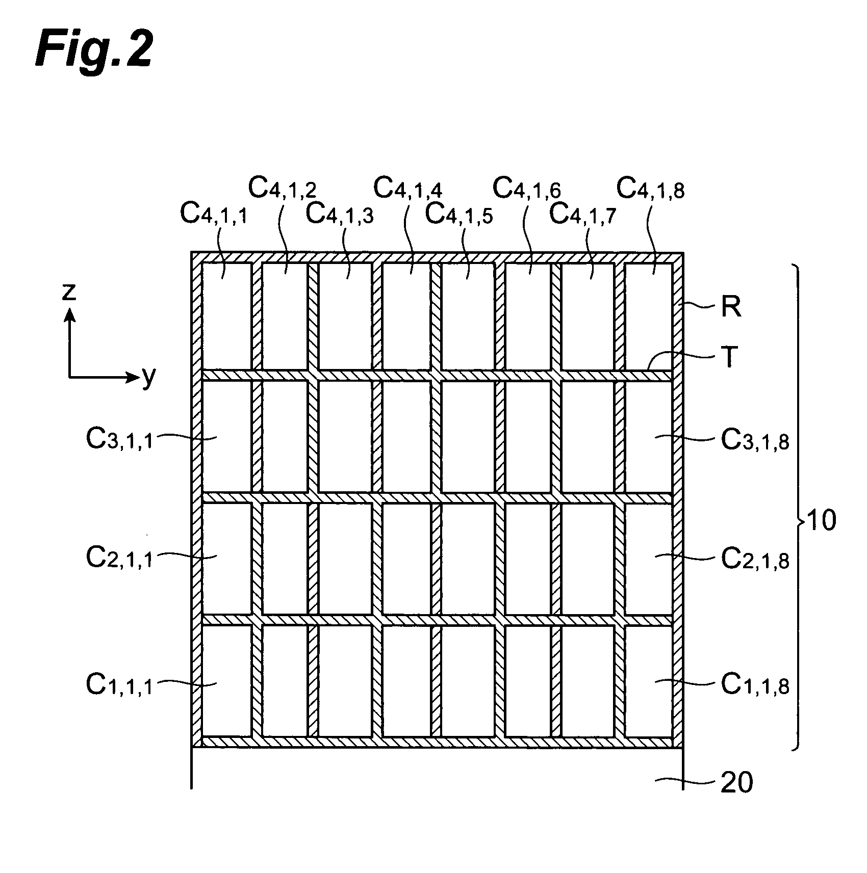
[0050]FIG. 2–FIG. 7 is a sectional view of the scintillator unit 10 respectively included in the radiation three-dimensional position detector 1 in accordance with the FIG. 2 is a y-z sectional view of the scintillator unit 10 in the first row (m=1). FIG. 3 is an x-z sectional view of the scintillator unit 10 in the first column (n=1). FIG. 4 is an x-y sectional view of the scintillator array 11 in the first layer (k=1). FIG. 5 is an x-y sectional view of the scintillator array 12 in the second layer (k=2). FIG. 6 is an x-y sectional view of the scintillator array 13 in the third layer (k=3) FIG. 7 is an x-y sectional view of the scintillator array 14 in the fourth layer (k=4) In these drawings, some scintillator cells only are given with a code Ck,m,n. And the scintillator cells with no code are identified with code Ck,m,n in which any one of the suffixes k, m and n is increased by 1 in order.

[0051]In the scintillator array 11 in the first layer, the medium between the scintillato...

second embodiment

[0068]FIGS. 13–20 are a sectional view respectively of the scintillator unit 10 included in the radiation three-dimensional position detector in accordance with the FIG. 13 is a y-z sectional view of the scintillator unit 10 in the first row (m=1). FIG. 14 is an x-z sectional view of the scintillator unit 10 in the first column (n=1). FIG. 15 is an x-y sectional view of a scintillator array 11 in the first layer (k=1). FIG. 16 is an x-y sectional view of a scintillator array 12 in the second layer (k=2). FIG. 17 is an x-y sectional view of a scintillator array 13 in the third layer (k=3). FIG. 18 is an x-y sectional view of a scintillator array 14 in the fourth layer (k=4) FIG. 19 is an x-y sectional view of a scintillator array 15 in the fifth layer (k=5). And FIG. 20 is an x-y sectional view of a scintillator array 16 in the sixth layer (k=5). In these drawings, some scintillator cells only are designated with a code Ck,m,n. And the scintillator cells with no code are identified ...


PUM


Abstract

The radiation three-dimensional position detector of the present invention comprises a scintillator unit (10), a light receiving element (20) and an operation section (30). The scintillator unit is disposed on the light incident plane of the light receiving element, wherein the scintillator unit is comprised of four layers of scintillator arrays, each layer being composed of scintillator cells arrayed in 8 row −8 column matrix. The scintillator cell produces scintillation light corresponding to the radiation absorbed thereby. The optical characteristic of a partition material for separating neighboring scintillator cells, which faces at least one same side face is different between a scintillator cell Ck1,m,n included in one scintillator array layer (k1-th layer) and a scintillator cell Ck2,m,n included in the other scintillator array layer (k2-th layer).

Description

BACKGROUND OF THE INVENTION[0001]1. Field of the Invention[0002]This invention relates to a radiation three-dimensional position detector including a scintillator unit and a light receiving element.[0003]2. Related Background Art[0004]The radiation three-dimensional position detector is used, for example, in a PET (positron emission tomography) apparatus as a radiation detector which detects pair of γ-ray photons (energy: 511 k eV), which is produced following on the pair annihilation of electron and positron within a subject to which a positron emission isotope (RI radiation source) is applied, and fly in the opposite directions with respect to each other. The PET apparatus detects pair of γ-ray photons with a radioactive transducer in a manner of simultaneous counting, and the simultaneously counted information is accumulated to create a histogram. Further, the PET apparatus, reconstructs, based on the created histogram, an image representing spatial distribution of the generative...

Claims


Application Information

Patent Timeline
Patent Type & Authority Patents(United States)
IPC IPC(8): G01T1/20G01T1/161G01T1/164
CPCG01T1/2008G01T1/1644
Inventor MURAYAMA, HIDEOINADAMA, NAOKOKITAMURA, KEISHIYAMASHITA, TAKAJI
Owner HAMAMATSU PHOTONICS KK
Why Eureka
Try Eureka