Correction of magnetic resonance images

a magnetic resonance and image correction technology, applied in the field of magnetic resonance imaging, can solve the problems of increasing non-linearity, increasing the difficulty of image translation and distortion, so as to avoid artifacts in brain images.

Inactive Publication Date: 2006-08-08
THE UNIV OF QUEENSLAND
View PDF6 Cites 30 Cited by
  • Summary
  • Abstract
  • Description
  • Claims
  • Application Information

AI Technical Summary

Benefits of technology

[0043]As with the first aspect of the invention, larger or smaller values of ε can be used in the practice of the invention, with larger values leading to reduced computation time and smaller values to increased time.
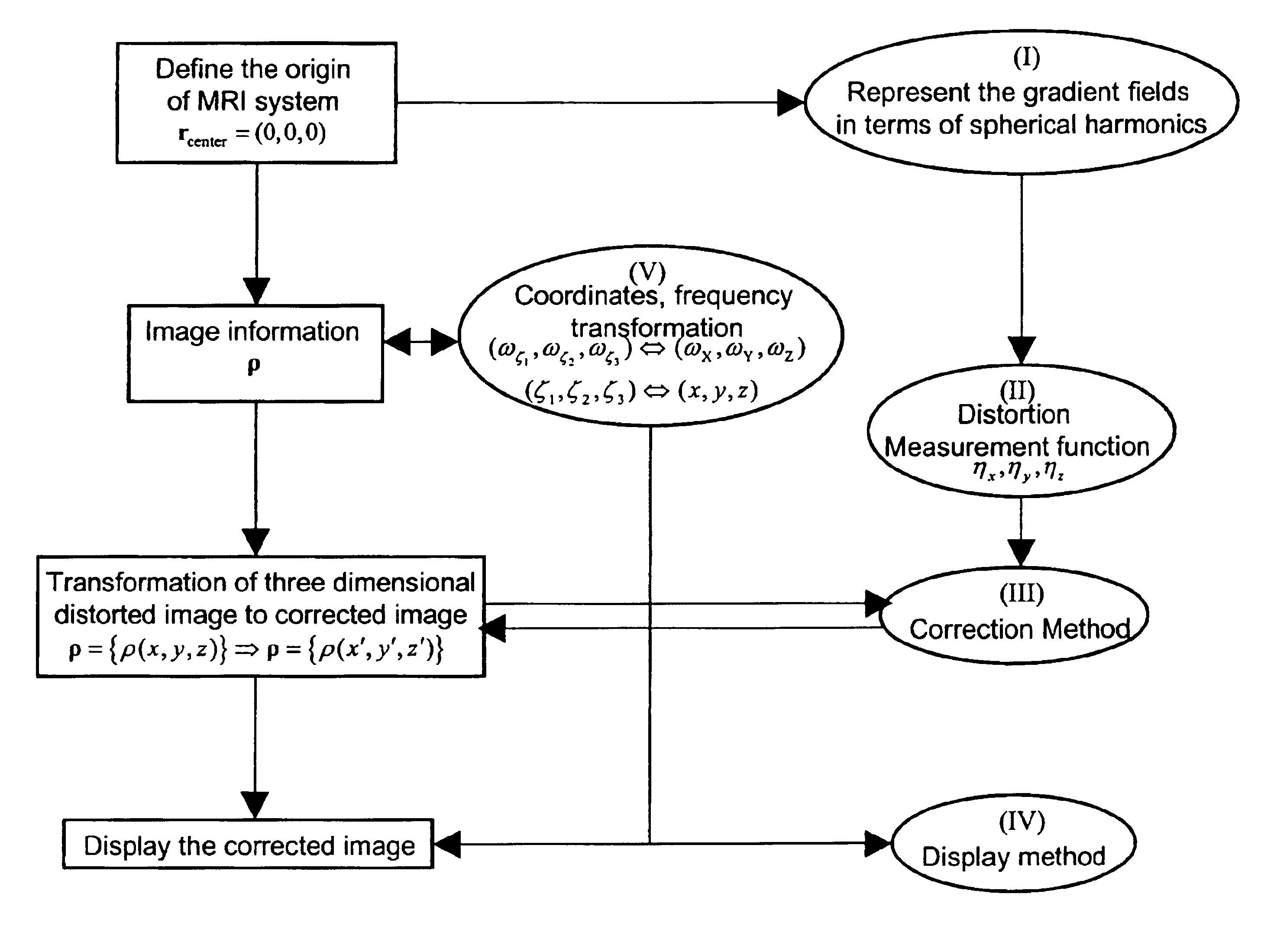
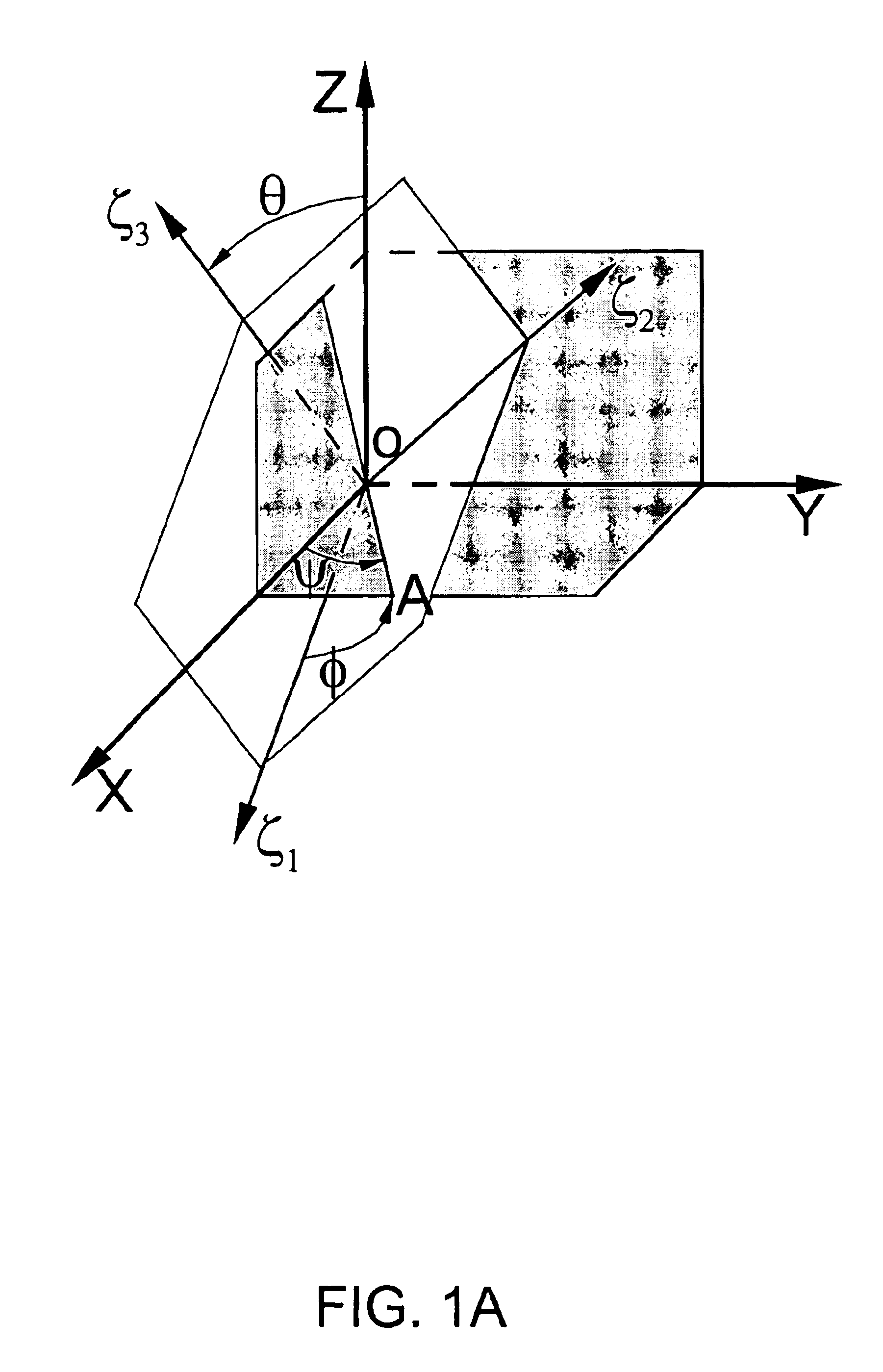
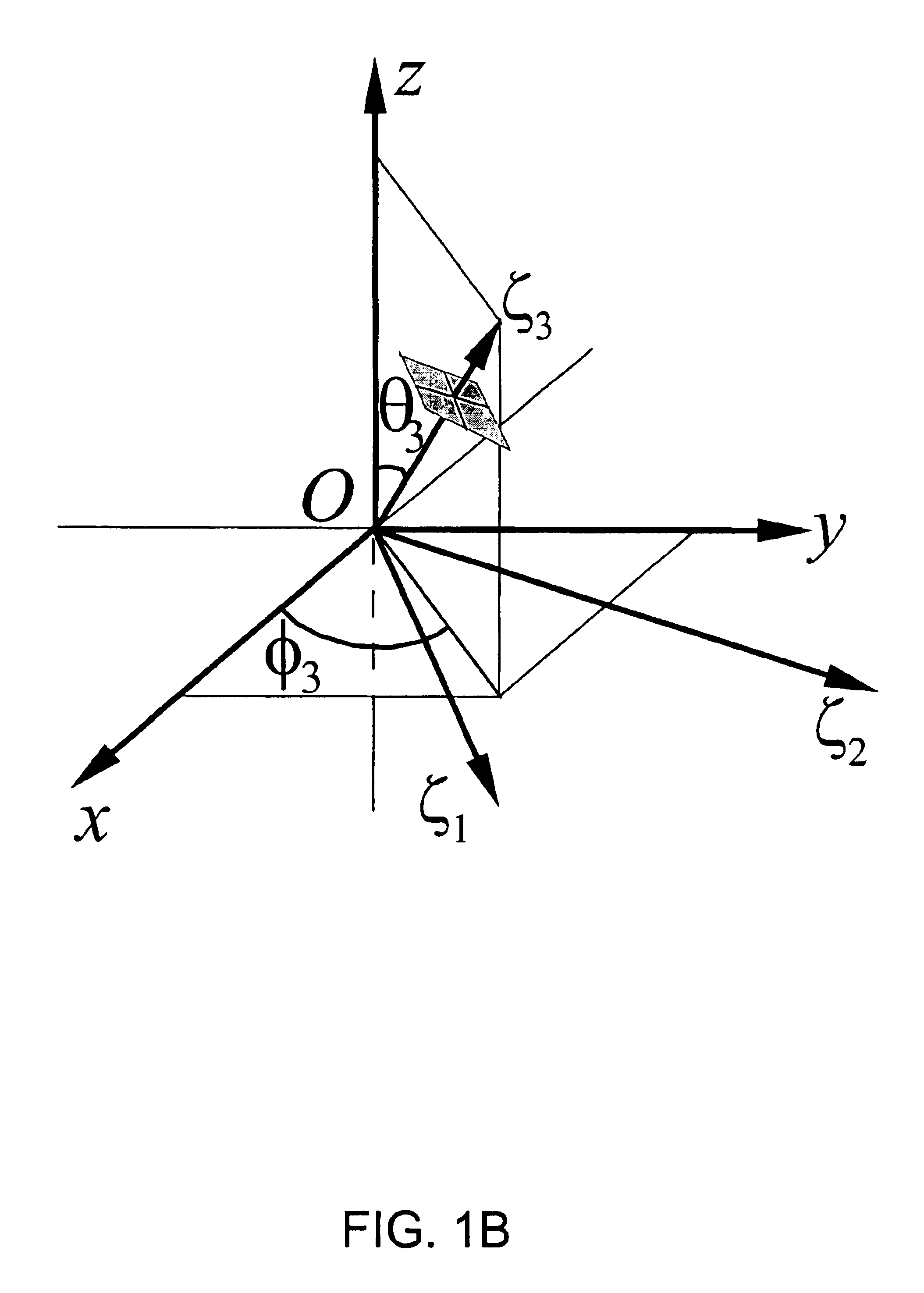
[0051]The first and second aspects of the invention have been described above in terms of correcting 3D imaging where the imaging coordinate system corresponds to the x,y,z-coordinate system. These aspects of the invention can also be used In the case of arbitrary 3D imaging, i.e., 3D imaging where the imaging coordinates are oriented in an arbitrary way with respect to the x,y,z-coordinate system. Such arbitrary 3D imaging can be of benefit in, for example, avoiding artifacts in brain images, specifically, in avoiding artifacts associated with the presence of air in nasal structures. The arbitrary 3D imaging is achieved in practice by selecting values for the X, Y, and Z gradient magnets which cause the imaging volume to have associated therewith a Cartesian coordinate system which is rotated relative to the x,y,z-coordinate system.
[0194]Look at another way, this aspect of the invention takes into account the translational and / rotational misalignment of the symmetry point and / or associated axes of least one of the field generating devices with the symmetry point and / or associated axes of at least one other of the field generating devices. This correction is above and beyond the correction of any basic inhomogeneity in the field generating devices themselves. That is, although the field generating devices in themselves may generate fields which are effectively homogeneous, i.e., a symmetric field in the case of the main magnet or an asymmetric field in the case of a gradient field, there can still be distortions in the resulting images because of translational and / or rotational misalignment of the symmetry points and / or associated axes of the generating devices. The present invention recognizes and addresses this problem so as to produce magnetic resonance images having reduced levels of distortion.
[0204]The coefficients having the largest magnitudes will have the largest effects in correcting the image, and thus at least those larger coefficients are preferably used in performing the image correction of step (C). Such larger coefficients can be selected by examining a table such as Table 2 for the coefficients with the largest magnitudes and then using those coefficients in step (C), beginning first with the largest 2 or 3 coefficients and continuing on from there as desired. Although using just the largest coefficients will work successfully, in general, using all of the above-listed coefficients is preferred since the additional computation time will, in general, be minimal.

Problems solved by technology

Radio frequency (rf) coil inhomogeneity results in non-uniform excitation of the nuclear spins resulting in intensity variations, while deviation from linearity of the gradient field from application of the pulsed field gradients induces image translation and distortions.
These limitations, although suitable for the implementation of pulse sequences having the desired speed, have the undesired consequence of increased non-linearity in the gradient fields.
The result is distorted images.
More particularly, non-linear pulsed field gradients induce image distortions due to incorrect spatial encoding of the signal.
However, any deviation from linearity in the gradients results in non-linear data sampling and subsequent errors in image spatial encoding.
Unfortunately, non-linear Fourier transformation greatly increases computation time by N / log2N, relative to a FFT, making real-time image generation computationally prohibitive.
Regardless, these approaches are of limited use in attempting to discern, model or correct distortion due to part of the MRI system in isolation, specifically, the gradients.
Whilst this approach is useful for gradients with a significant length to diameter ratio (>2), it is of limited use with current high-speed gradients with significant higher order gradient field impurities.
The method proposed involves approximately 1014 triple integrations and thus is of limited practical value.
Indeed, this patent publication highlights one of the primary deficiencies in the art—namely, the failure to realize that any method, which is of practical value, must use the FFT as its basis.
Such translational and rotational misalignments in and of themselves produce distortions in MR images.
Winding and / or design errors for the field generating devices are another source of distortion (the winding error problem).

Method used


Image

  • Correction of magnetic resonance images
  • Correction of magnetic resonance images
  • Correction of magnetic resonance images

Examples


example 1

A. Example 1

[0289]A set of high speed SONATA gradients manufactured by SIEMENS AKTIENGESELLSCHAFT in Germany was analyzed. The set of SONATA gradients was interfaced to an OXFORD MAGNET TECHNOLOGY 4T whole body magnet and the gradient inhomogeneities were measured using a 24 plane spherical harmonic deconvolution NMR plot. The shimmed magnet was plotted first, followed by two more plots in which a constant current was applied to the X and Z gradients respectively. The harmonics for the shimmed field were subtracted from those generated by the gradients. For simplicity, in this case, it was assumed that the X and Y gradient distortions were identical.

[0290]The harmonics of interest are listed in Table 1A. Only 4th order harmonics are listed as this was sufficient for image correction. For reference, Table 1B shows the harmonics to 7th order. The magnetic field distributions for the X, Y, and Z gradients are shown in FIG. 11.

[0291]It is clear from these isomagnetic plots that the grad...

example 2

B. Example 2

[0298]As discussed in Example 1, a spherical harmonic deconvolution of the X, Y, Z gradients of a SONATA gradient set was carried out at 4T. It was assumed that the same gradient impurities are present with all manufactured SONATA gradients and the harmonic deconvolution of the gradients at 4T can be used to correct images acquired using a 1.5T SIEMENS SONATA scanner. Otherwise, as discussed above, the particular gradients for a given scanner should be mapped and stored in a look-up table and applied to correct distorted images.

[0299]Imaging experiments to assess gradient linearity were performed using a phantom manufactured by BRUKER MEDICAL in Germany. This phantom consists of a cylinder having perfectly flat ends. The diameter of the phantom is 18.5 cm and the depth 3 cm. Within the phantom there are point markers, the spacing between which is a known distance, namely, 2 cm for the main grid. Imaging was performed at 1.5T using a turbo spin echo sequence with a 256×25...


PUM


Abstract

Spatial encoding in magnetic resonance imaging (MRI) techniques is achieved by sampling the signal as a function of time in the presence of magnetic field gradients, e.g., X, Y, and Z gradients. The gradient magnets have in the past been assumed to generate a linear gradient, and typical image reconstruction techniques have relied upon this assumption. However, to achieve high speed performance, gradient magnets often sacrifice linearity for speed. This non-linearity, in turn, results in distorted images, the distortion often being sufficiently large to compromise the usefulness of MRI images for stereotaxy or longitudinal studies, where precise volumetric information is required. The disclosure provides practical methods for correcting distorted images resulting from such non-linearity in the gradient fields, as well as distortions resulting from translational, rotational, and / or winding / design errors in the field generating devices. The methods employ spherical harmonic expansions of the gradient fields and fast Fourier transform techniques to provide well-corrected images without undue computational burdens.

Description

I. FIELD OF THE INVENTION[0001]This invention relates to magnetic resonance imaging (MRI). In particular, the invention is directed to the use of spherical harmonic deconvolution methods to compensate for the effects on MRI images of (i) non-linear gradients (hereinafter referred to as the “non-linear problem”), (ii) misalignments of the symmetry points of one or more of the MR system's field generating devices, i.e., the main (B0) magnet, the X-gradient magnet, the Y-gradient magnet, and the Z-gradient magnet (hereinafter referred to as the “non-coincident center problem”), (iii) deviations from ideal geometric alignment of the field generating devices (hereinafter referred to as the “axes misalignment problem”), and (iv) winding and / or design errors of the field generating devices (hereinafter referred to as the “winding error problem”).II. BACKGROUND OF THE INVENTION[0002]The quality of images in magnetic resonance imaging is dependent upon the homogeneity of the respective instr...

Claims


Application Information

Patent Timeline
Patent Type & Authority Patents(United States)
IPC IPC(8): G01V3/00A61B5/055G01R33/565
CPCG01R33/56518A61B5/7257A61B5/055G01R33/56572
Inventor DODDRELL, DAVID M.ZHAO, HUAWEI
Owner THE UNIV OF QUEENSLAND
Why Eureka
Try Eureka