Process cartridge and electrophotographic image forming apparatus
a process cartridge and electrophotography technology, applied in the field of electrophotography image forming apparatus and process cartridge, can solve the problems of inability to produce high-quality images, electrical current will leak to any of the electrical components, etc., and achieve the effect of reducing the distance between the charging member and the process cartridge siz
- Summary
- Abstract
- Description
- Claims
- Application Information
AI Technical Summary
Benefits of technology
Problems solved by technology
Method used
Image
Examples
embodiment 1
[General Structure of Color Image Forming Apparatus]
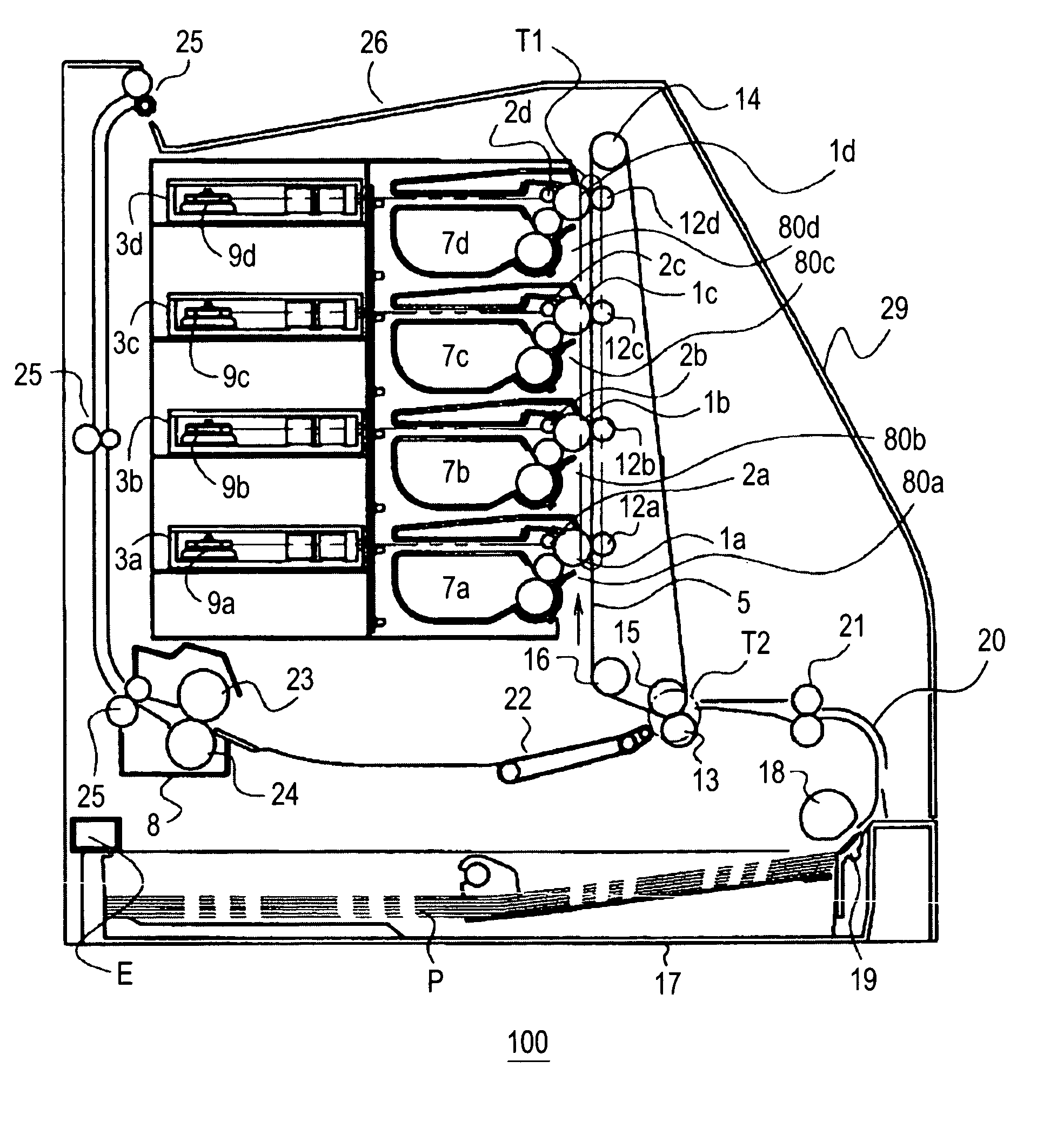
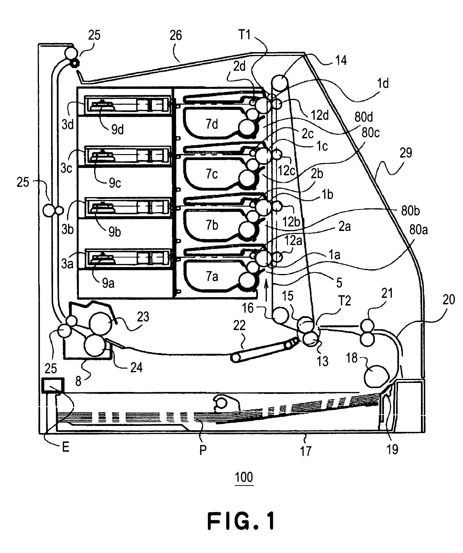
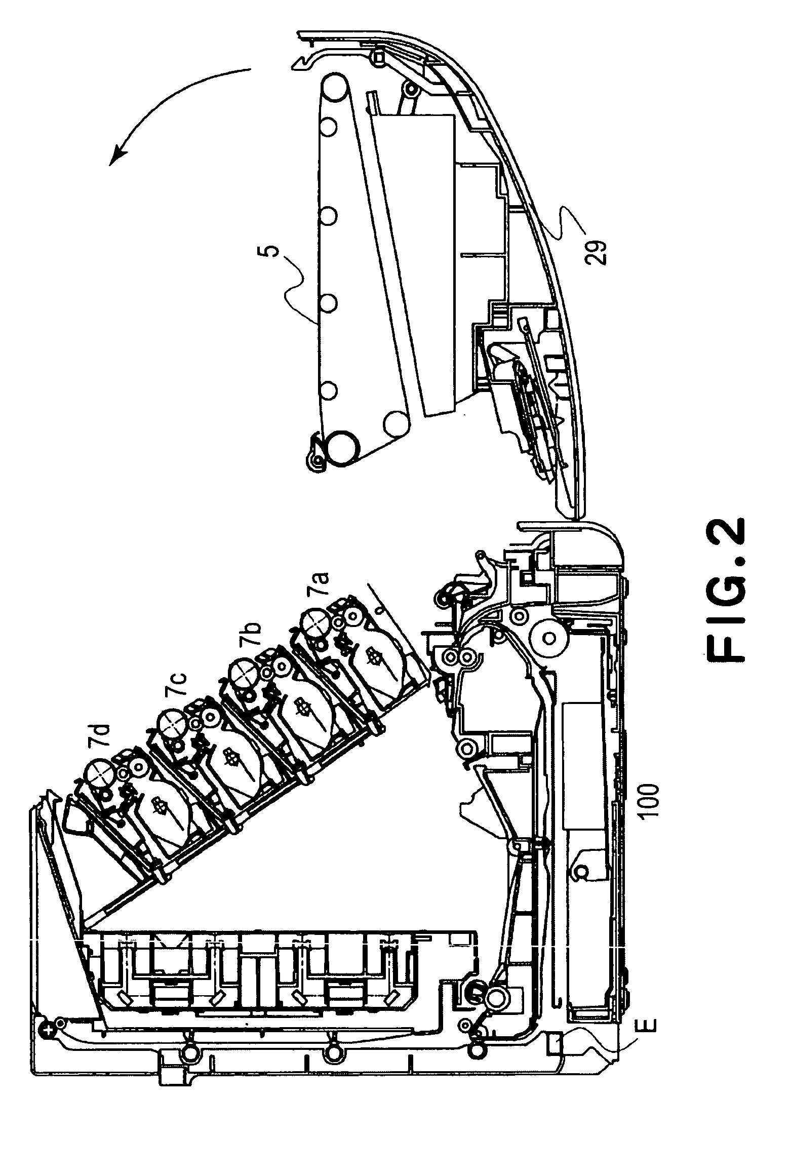
[0033]First, referring to FIGS. 1–3, the general structure of a typical color image forming apparatus will be described. FIGS. 1 and 2 are drawings for describing the overall structure of a full-color laser printer as an example of a color image forming apparatus, and FIG. 3 is a drawing for depicting the overall structure of the process cartridge employed by the full-color laser printer.
[0034]Referring to FIG. 1, the color laser printer comprises four process cartridges 7 (one for each of color components: yellow, magenta, cyan, and black), and an intermediary transferring member 5. Each process cartridge 7 has an electrophotographic photosensitive drum. The intermediary transferring member 5 bears the multiple color toner images developed by the process cartridges 7 and transferred onto the intermediary transferring member 5, and transfers the toner images onto a recording medium P delivered from a recording medium feeding portio...
embodiment 2
[0084]Next, referring to FIGS. 13, 14, and 15, another embodiment of the present invention will be described. FIG. 13 is an enlarged view of one of the lengthwise ends of the charge roller 2, and its adjacencies, showing in detail the structures thereof, and FIG. 14 is a drawing depicting the relationship between the charge roller 2 and sheet 71 in terms of the their lengthwise direction. FIG. 15 is a drawing depicting the relationship between the charge roller 2 and sheet 71.
[0085]In this embodiment, the drum cleaning member 60 is attached to the frame 61 with the use of two-sided adhesive tape (unshown), instead of the pair of small screws.
[0086]Also in this embodiment, the sheet 71 extends beyond both lengthwise ends 2t1 of the contact area 2t, reaching the range of the portions of the metallic shaft 2s exposed from the roller portion 2r. Therefore, electric current is prevented from leaking from the charge roller 2 to the base 60a (electrically conductive member) as the cleaning...
PUM
 Abstract
Description
Claims
Application Information
 - R&D
- Intellectual Property
- Life Sciences
- Materials
- Tech Scout
- Unparalleled Data Quality
- Higher Quality Content
- 60% Fewer Hallucinations
Browse by: Latest US Patents, China's latest patents, Technical Efficacy Thesaurus, Application Domain, Technology Topic, Popular Technical Reports.
© 2025 PatSnap. All rights reserved.Legal|Privacy policy|Modern Slavery Act Transparency Statement|Sitemap|About US| Contact US: help@patsnap.com


