
Two stage detector having viterbi detector matched to a channel and post processor matched to a channel code

a technology of post processor and viterbi detector, which is applied in the field of information detection, can solve the problems of viterbi detector requiring a very complex implementation, detection errors at the output of viterbi detector, and overload of outer ecc process,

Inactive Publication Date: 2006-08-08
SEAGATE TECH HDD HLDG +3
View PDF21 Cites 27 Cited by
  • Summary
  • Abstract
  • Description
  • Claims
  • Application Information

AI Technical Summary

Benefits of technology

[0015]More particularly, an object of the present invention provides a detection architecture and method for increasing the performance of a partial response channel by correcting most likely error-events in a way that is not too complicated.
[0017]A further object of the present invention is to provide an improved two-stage detection architecture for a magnetic recording and playback channel which may be practically implemented in a read channel large scale integrated circuit chip.

Problems solved by technology

Noise added into the partial response channel could cause detection errors at the output of the Viterbi detector.
It may be the case, particularly at high recording densities, that so many errors are made in the detection process that the outer ECC process is overwhelmed and becomes incapable of locating and / or correcting all of the error bursts.
Implementing a channel code that provides performance gain at high code rate has previously resulted in a Viterbi detector requiring a very complex implementation, since prior Viterbi detectors have been matched to both the channel characteristics and to the channel code constraints.
And in this first case the Viterbi is not necessarily matched to the code, because the code is not providing error detection or correction capability.
Channel noise can cause errors at the output of the Viterbi detector.
Errors may be more likely to occur at higher magnetic recording densities.
In the past, many channel codes have not achieved significant performance gains because of low code rate and because the code may not have been optimized for the error-events or error patterns that are most likely to occur within a particular partial response channel.
While rates were slowly increasing for trellis codes, they generally had a lower code rate than more efficient codes which were not useful for detecting or correcting error-events.
One drawback of the Fredrickson '272 patent approach was its relatively complex Viterbi detector structure.
As the number of states in the channel increases, the complexity of the combined detector increases seven-fold.

Method used


Image

  • Two stage detector having viterbi detector matched to a channel and post processor matched to a channel code
  • Two stage detector having viterbi detector matched to a channel and post processor matched to a channel code
  • Two stage detector having viterbi detector matched to a channel and post processor matched to a channel code

Examples


Embodiment Construction

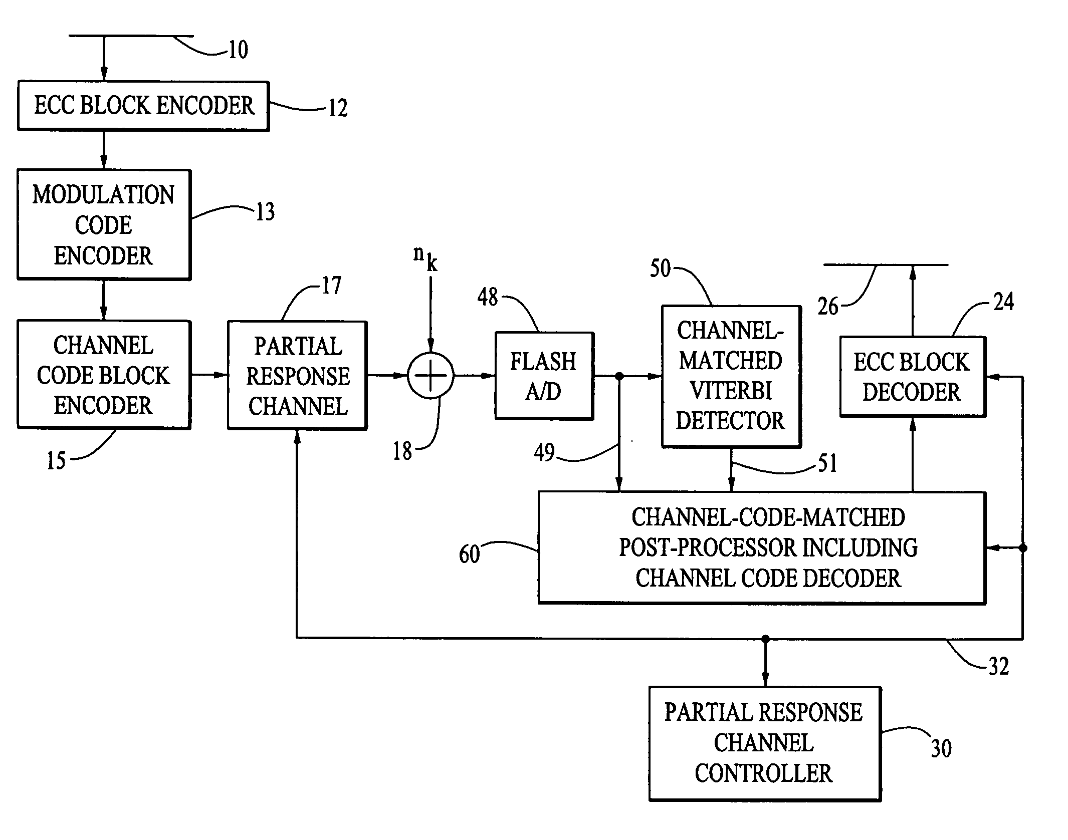
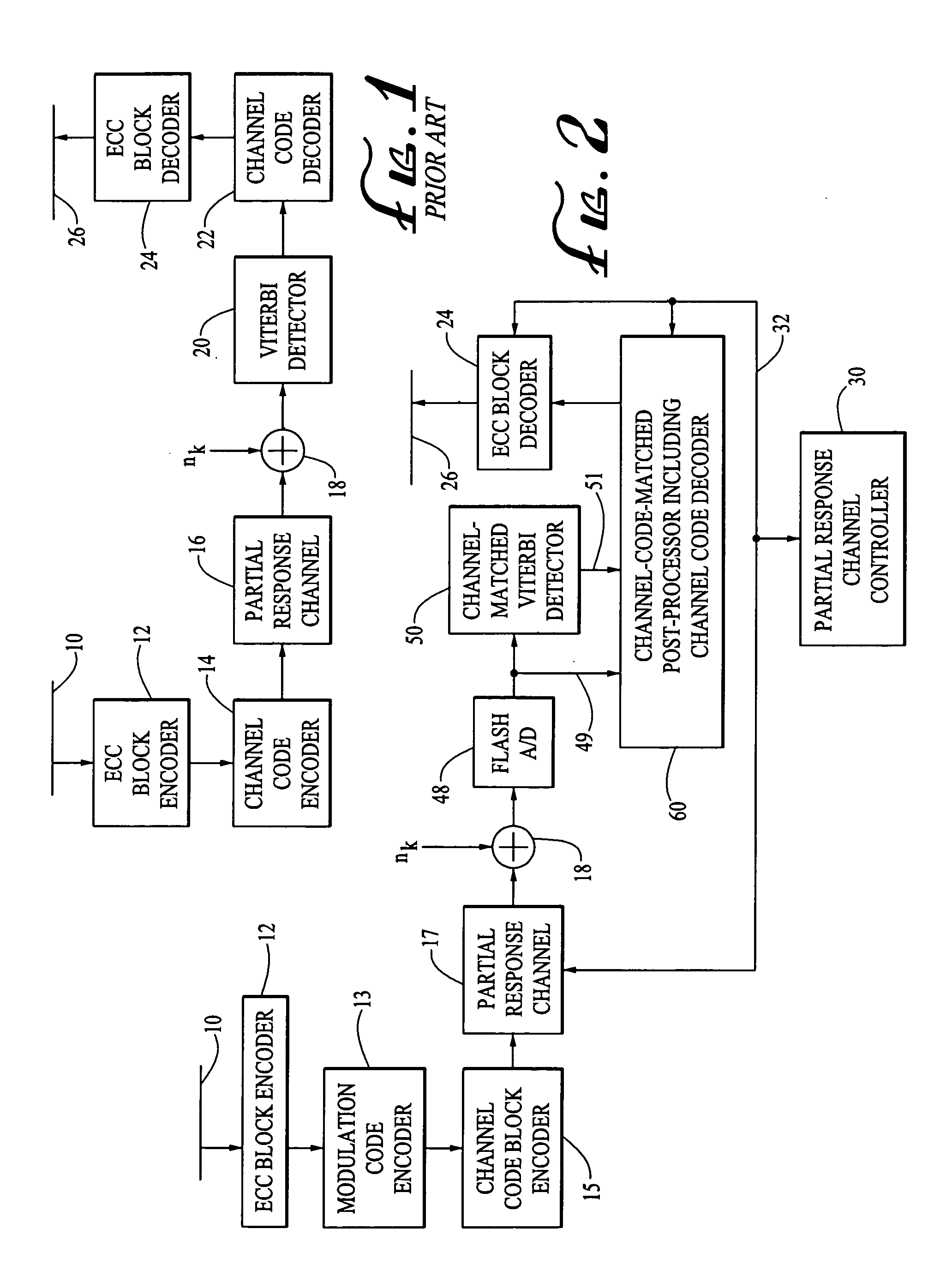
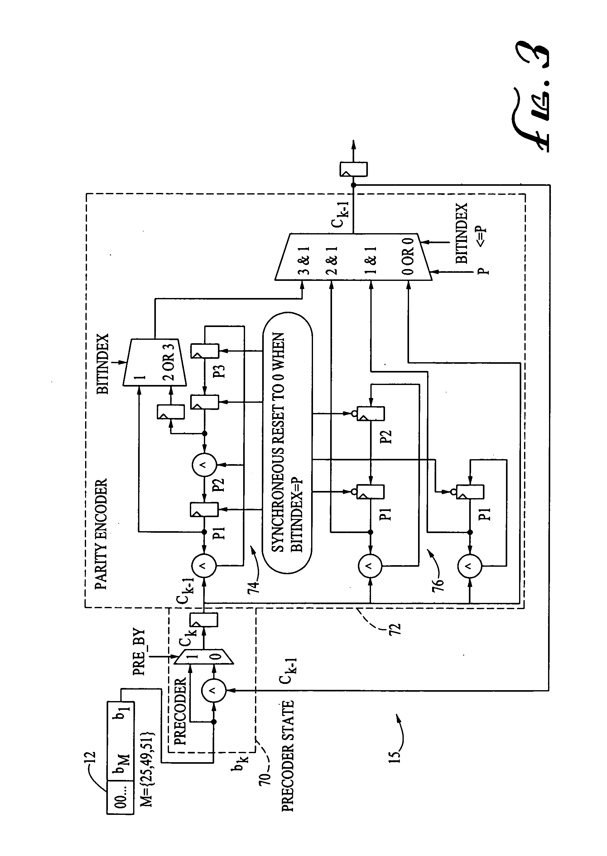
[0034]In order to better understand and appreciate principles of the present invention, a conventional partial response channel is described in connection with the FIG. 1 block diagram. In FIG. 1 an information bus 10 supplies digital values to an error correction code (ECC) encoder 12. The encoder 12 processes a user data block, having a predetermined block length such as e.g. approximately 4096 bits, and generates and appends certain ECC 8 or 10 bit length redundancy symbols onto the user data block, depending upon a particular ECC algorithm being implemented, such as a Reed-Solomon code. The user block ECC algorithm is conventional, is well understood by those skilled in the art, and is not described in further detail in connection with the present invention. The user data values including the appended ECC redundancy symbols are passed to a channel code encoder 14 wherein the user data values and ECC symbols are further encoded in accordance with a predetermined channel code havi...


PUM

PropertyMeasurementUnit
discrete-time transfer functionaaaaaaaaaa
unit time delayaaaaaaaaaa
magneticaaaaaaaaaa

Abstract

A two-stage sampling data detector for a partial response channel having a channel code encoder for encoding user information sequences into blocks of code words in accordance with a predetermined channel block code characterized by a list of most likely error-events comprising impermissible code words. The detector includes a first-stage detector, such as a Viterbi detector, connected to receive samples from the partial response channel and matched to characteristics of the channel and not to the channel code, puts out unchecked bit estimates. A second stage post-processor checks the bit estimates in relation to derived detector decision metrics information and the channel block code, and puts out post-processed bit estimates to a channel code decoder after correcting detected erroneous sequences in accordance with the decision metrics information, information derived from the channel code, and the list of most likely error-events. A method for generating the channel block code is also described.

Description

CROSS REFERENCE TO RELATED APPLICATION[0001]This is a divisional of U.S. patent application Ser. No. 09 / 352,160 filed Jul. 12, 1999 now U.S. Pat. No. 6,732,328. The entire disclosure of U.S. patent application Ser. No. 09 / 352,160 is incorporated herein by reference.FIELD OF THE INVENTION[0002]This invention relates to the detection of information within a sampled data detection channel, such as a magnetic recording and playback channel. More particularly, the present invention relates to a first stage maximum likelihood detector implementing the Viterbi detection algorithm adapted only to channel characteristics, and a second stage post-processor adapted to check and correct detection results based upon an embedded channel code imposed on the information within the channel by a channel code encoding process.BACKGROUND OF THE INVENTION[0003]A partial response maximum-likelihood (PRML) channel with Viterbi detection is a high performance architecture used for detection of a signal e.g...

Claims


Application Information

Patent Timeline
Patent Type & Authority Patents(United States)
IPC IPC(8): H03M13/03G11B20/18H03M13/41H04L1/00
CPCG11B20/18H03M13/41H04L1/0071H03M13/6343H03M13/6502H04L1/0054H03M13/6331G11B2020/1863
Inventor MCEWEN, PETERFITZPATRICK, KELLY
Owner SEAGATE TECH HDD HLDG
Learn More