
Process of manufacturing coil layers using a novel combination of photoexposure and thermal curing to achieve shape control of a photoresist material

a photoresist material and manufacturing process technology, applied in the field of fabrication of thin film magnetic write head, can solve the problems of poor resistance and inductance value yield, lack of specific instruction on how to form a photoresist layer, and new problems with insulation layer and multiple coil layers, so as to reduce coil pitch, reduce coil to pole shorting, and improve product yield

Inactive Publication Date: 2006-08-15
HEADWAY TECH INC
View PDF10 Cites 1 Cited by
  • Summary
  • Abstract
  • Description
  • Claims
  • Application Information

AI Technical Summary

Benefits of technology

[0011]A second object of this invention is to provide a method for forming coil insulation layers and multiple coil layers for magnetic write heads having ultra-short yoke lengths in the range of 15 μm and below, wherein product yield is improved and problems associated with coil resistance, coil inductance and intra-and inter-coil shorting as well as coil to pole shorting are reduced or eliminated.
[0012]A third object of this invention is to provide a method for forming coil insulation layers and multiple coil layers for magnetic write heads having ultra-short yoke lengths in the range of 15 μm and below, wherein it does not become necessary to reduce coil pitch and wherein a smaller yoke length (YL) can be achieved and a desired apex angle maintained.
[0013]A fourth object of this invention is to provide such a method wherein coil insulation layers are efficiently and cost-effectively formed using commercially available photoresist mediums.

Problems solved by technology

This shape is highly disadvantageous for the formation of a second magnetic coil layer and not only makes such second coil formation nearly impossible but also causes electrical shorting between the turns and between the turns and the magnetic pole yoke, leading to poor yields in terms of resistance and inductance values.
The method of Chang et al., however, does not specifically teach how to form a photoresist layer that defines the insulated coil structures that are formed beneath the upper yoke.
In addition, Han et al. do not disclose the yoke dimensions of their write head, so it is not known if it is an ultra-short write head,
As has already been pointed out, new problems with insulation layers and multiple coil layers arise in the context of ultra-short yoke lengths.
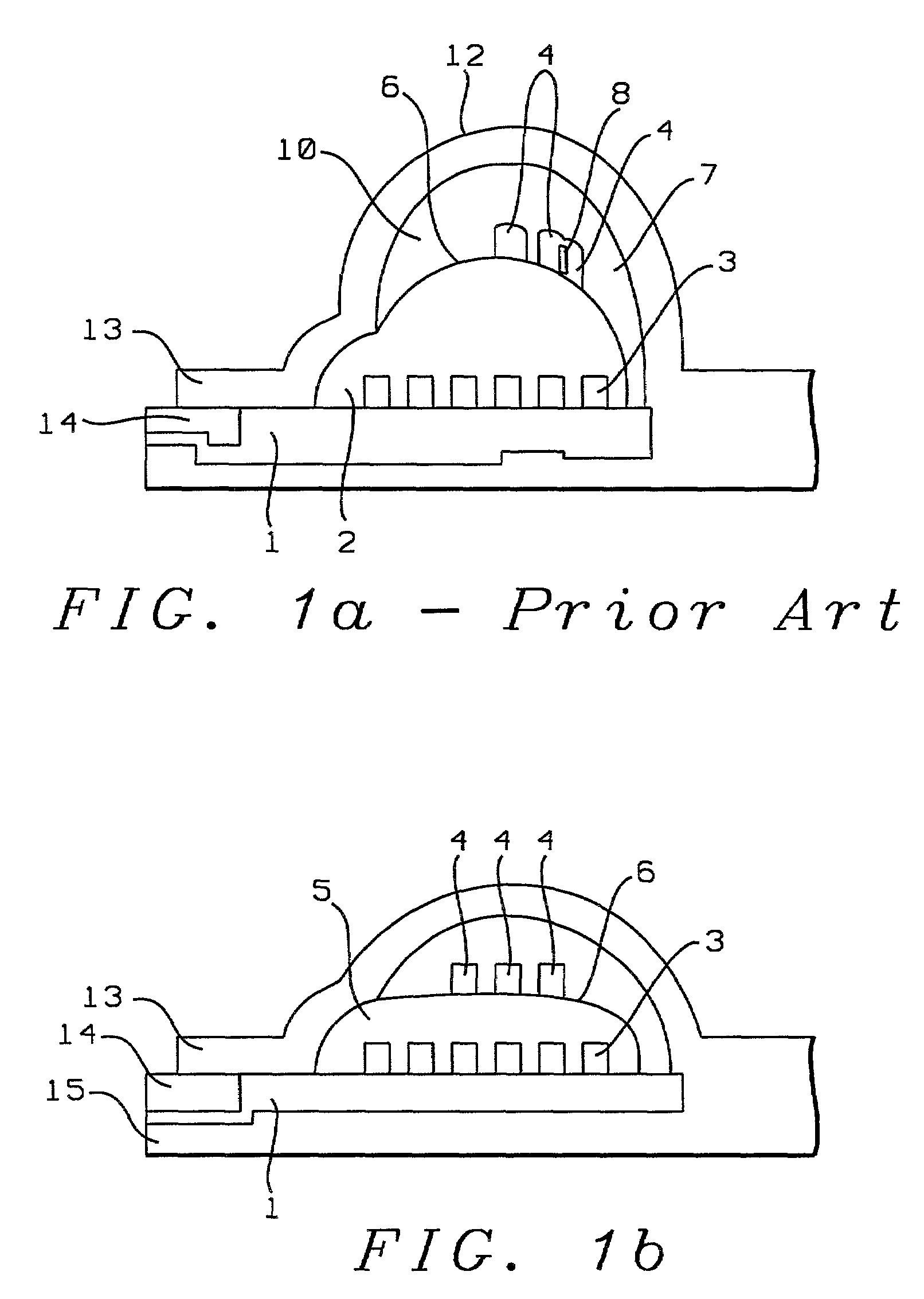
In these cases, the surface tension of the photoresist layer that forms the insulation layer produces a convex surface on which it is extremely difficult to form a second coil layer.
The prior art cited above does not address ultra-short yoke length fabrications and is, therefore, silent on the issue of photoresist surfaces and coil formation under those conditions.

Method used


Image

  • Process of manufacturing coil layers using a novel combination of photoexposure and thermal curing to achieve shape control of a photoresist material
  • Process of manufacturing coil layers using a novel combination of photoexposure and thermal curing to achieve shape control of a photoresist material
  • Process of manufacturing coil layers using a novel combination of photoexposure and thermal curing to achieve shape control of a photoresist material

Examples


Embodiment Construction

[0020]The present invention provides a method for forming coil structures and their resistive and support layers for an ultra-short yoke magnetic write head.

[0021]Referring first to FIG. 1 there is shown an artists rendering (for clarity of reproduction) of a photomicro graph of a cross-section through an ultra-short yoke magnetic write head formed by the methods of the prior art in which there is only a single hardbake of each insulating layer. A first coil layer (3) has been formed on an alumina (Al2O3) layer (1). A first layer of insulation (5) has been formed over the first coil layer by the prior art method, producing a convex upper surface (6) as a result of the hardbake. While a desired apex angle (2) has been obtained, the second coil layer (4) has been formed on the extremely convex surface (6) of the insulating layer of the first coil formation (5). As can also be seen, the necessity of forming the second coil layer (4) on such a convex surface has produced a poor coil for...


PUM

PropertyMeasurementUnit
time durationaaaaaaaaaa
energyaaaaaaaaaa

Abstract

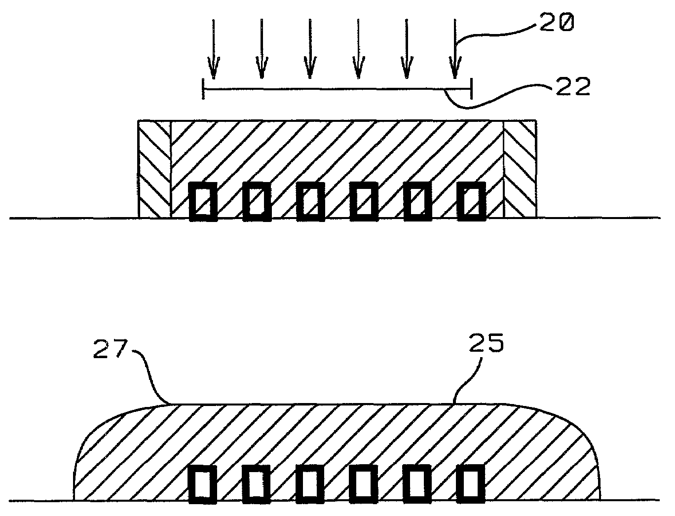
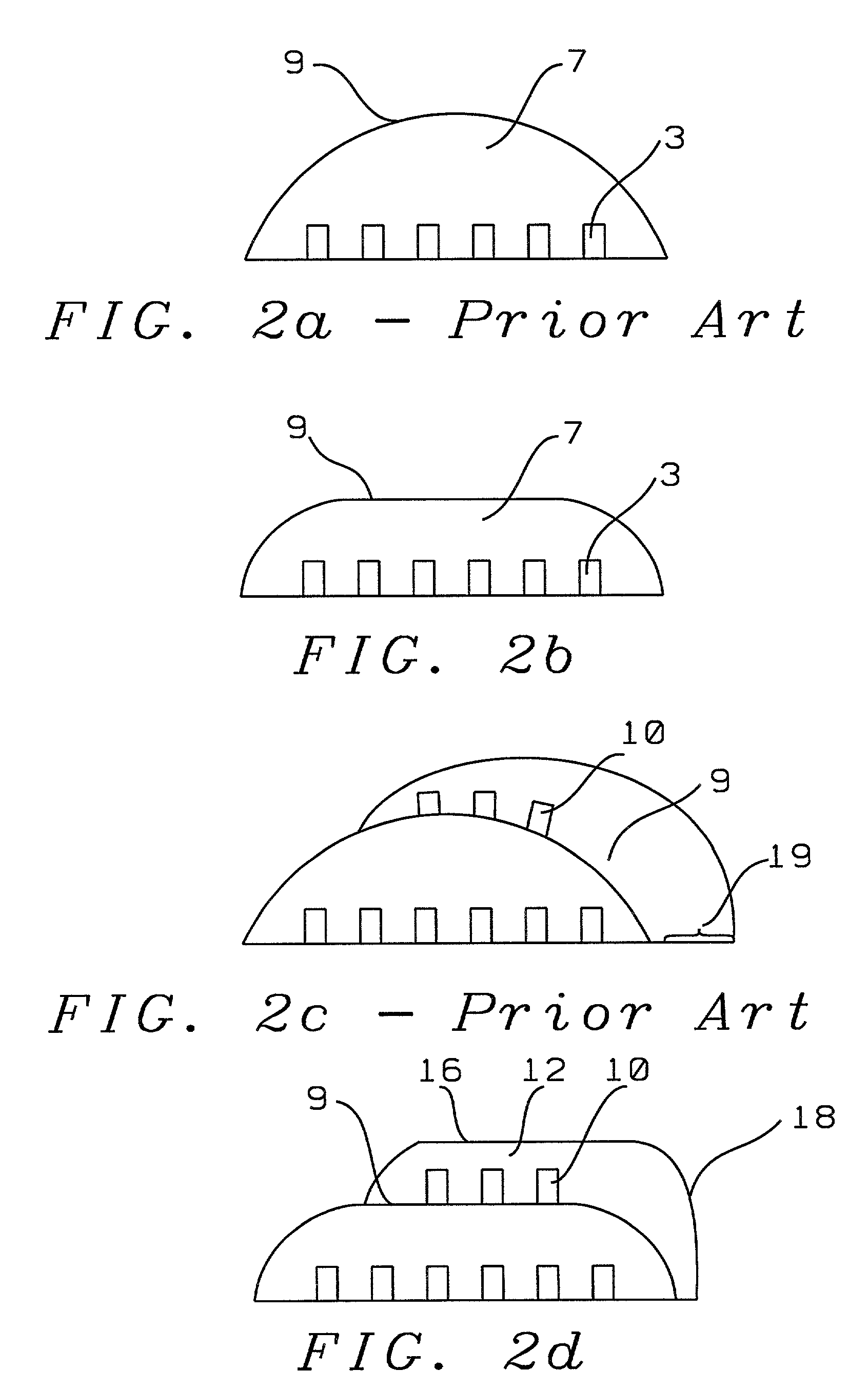
A method for forming at least two layers of electrical coils and their supportive resistive layers for a magnetic write head having an ultra-short yoke so that the second and any additional coil layers are formed on flat resistive surfaces to eliminate problems associated with inter- and intra-layer shorting and with shorting between coil and yoke. The resistive layers are formed with flat surfaces and desired apex angles by using a novel two-step photoresist scheme in which a layer of photoresist is first photoexposed and developed, then photoexposed a second time to cure a surface region that will remain flat during a final low temperature curing process.

Description

BACKGROUND OF THE INVENTION[0001]1. Field of the Invention[0002]This invention relates generally to the fabrication of a thin film magnetic write head and more particularly to the use of a novel photoresist process that permits an improved fabrication process for such heads having ultra-short yokes.[0003]2. Description of the Related Art[0004]The size reduction of yoke length (YL) in thin film head (TFH) magnetic write heads to lengths less than 15 microns (μm) has necessitated the development of methods for obtaining flat insulator topographies. The short YL insulator resist imaging process currently used in the TFH fabrication industry results in a convex shape after thermal hardbake of the resist (FIG. 1). This shape is highly disadvantageous for the formation of a second magnetic coil layer and not only makes such second coil formation nearly impossible but also causes electrical shorting between the turns and between the turns and the magnetic pole yoke, leading to poor yields ...

Claims


Application Information

Patent Timeline
Patent Type & Authority Patents(United States)
IPC IPC(8): G11B5/17G03F7/00G11B5/31
CPCG11B5/3116G11B5/313G11B5/3163G11B5/17Y10T29/49034Y10T29/49064Y10T29/49073Y10T29/49062Y10T29/4906
Inventor ZHENG, YILIU, YI-CHUN
Owner HEADWAY TECH INC
Learn More