
Hale-machining method and apparatus

a technology of hale-machine and machine, which is applied in the direction of grinding drives, manufacturing tools, lenses, etc., can solve the problems of not hale-machine the machined surface, the lens is complex in function and shape, and the die is a lot of lens and die for the lens machined, so as to achieve high geometric accuracy and facilitate the preparation of a nc machining program

Inactive Publication Date: 2006-08-15
TOYODA MASCH WORKS LTD
View PDF11 Cites 45 Cited by
  • Summary
  • Abstract
  • Description
  • Claims
  • Application Information

AI Technical Summary

Benefits of technology

[0008]In view of the previously mentioned circumstances, it is an object of the present Invention to provide a hale-machining method and apparatus thereof achieving an easy preparation of a NC machining program and performing a high geometrical accuracy in the predetermined three-dimensional free curved surface.
[0009]It is second object of the present invention to provide a hale-machining method and apparatus thereof performing a high geometrical accuracy by adjusting a cutting point finely.
[0010]It is third object of the present invention to provide a hale-machining apparatus performing a high geometrical accuracy by a simple construction and a high rigidity.

Problems solved by technology

Recently, it becomes for a lens to be complex in a function and a shape, and there appears a lot of lens and die for the lens machined by hale-machining.
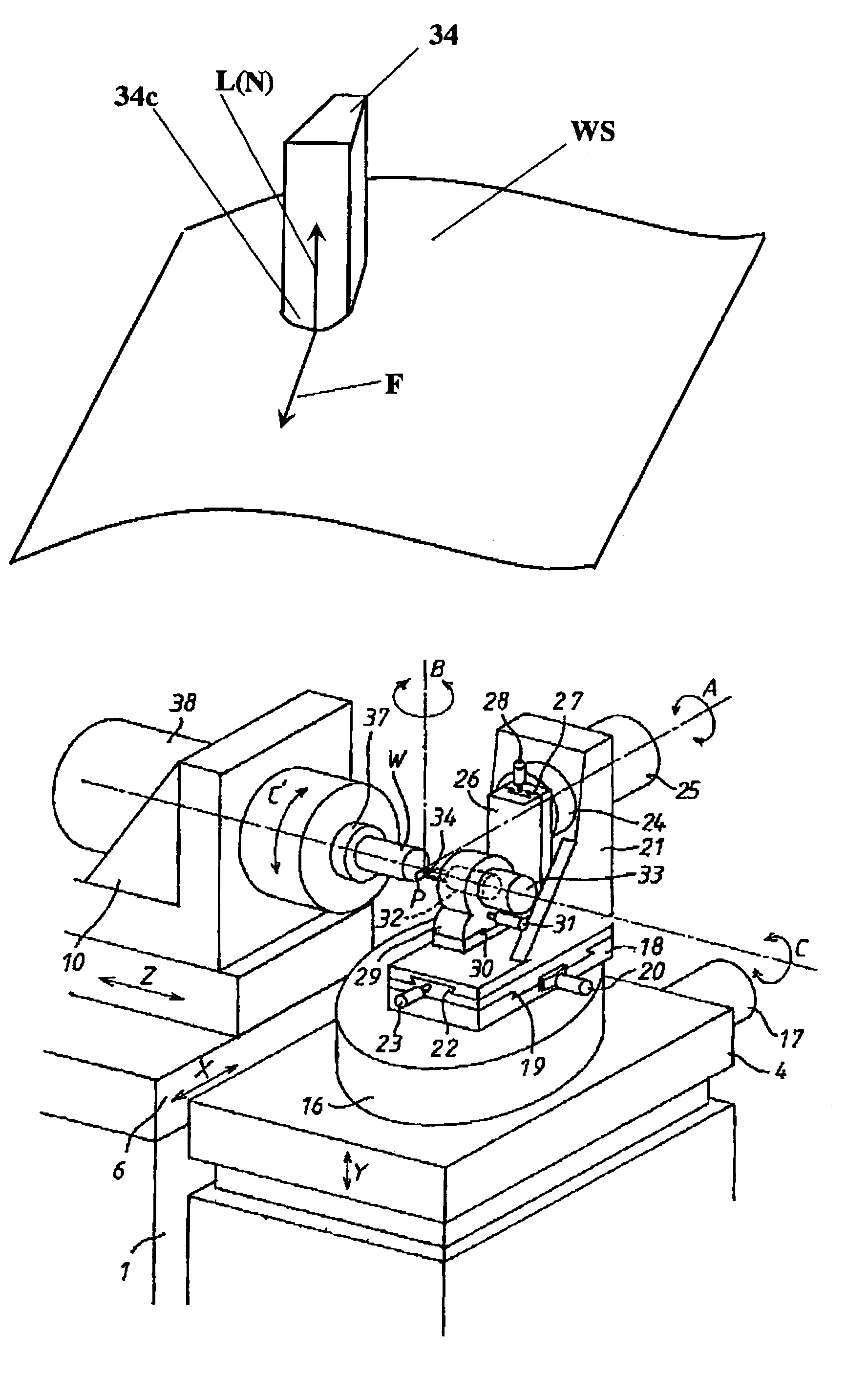
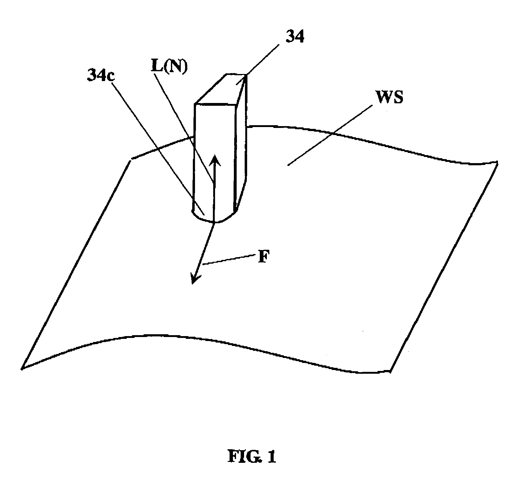
However, the well-known high precision machine is not provided with mechanical means to swing or rotate right and left the workpiece or the haling tool around an A-axis parallel to the X-axis, therefore, the well-known precision machine can not hale-machine the machined surface of the workpiece in three-dimensional curved surface because the front rake surface of the haling tool can not be substantially maintained at the perpendicular angle to the cutting feed direction F at any time.
Although the well-known precision machine can hale-machine a two-dimensional surface of the workpiece by the haling tool, however, since the cutting point is far from a center of the C′-axis in cutting a peripheral portion on the workpiece, it is needed to provide an interpolation control in the C′-axis, the X-axis and the Y-axis so that it makes the controller complex.

Method used


Image

  • Hale-machining method and apparatus
  • Hale-machining method and apparatus
  • Hale-machining method and apparatus

Examples


Embodiment Construction

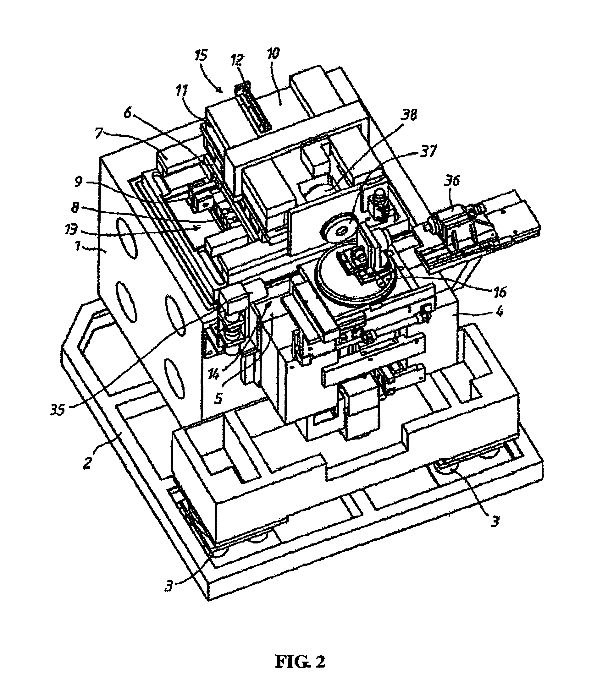
[0020]A preferred embodiment of the hale-machining method and apparatus according to the present invention will be described referring to FIG. 2 to FIG. 3. In FIG. 2 and FIG. 3, a bed 1 is mounted on a base 2 through a vibration isolator 3. On a front surface of the bed 1 is provided a Y-axis slide table 4 straightly movable in up / down Y-axis direction by being guided with a guide mechanism 5. The Y-axis slide table 4 is straightly moved by an un-illustrated linear motor at the Y-axis direction and a position thereof is controlled by detecting a movement amount of the Y-axis slide table 4 by an un-illustrated linear scale as a feedback data. An X-axis slide table 6 is mounted on a horizontal surface of the bed 1 to be straightly movable in right / left X-axis direction by being guided with a guide mechanism 7. The X-axis slide table 6 is moved straightly by a linear motor 8 in the X-axis direction and a position thereof is controlled by detecting a movement amount of the X-axis slide ...


PUM


Abstract

It is one object of a hale-machining method and apparatus thereof according to the present invention to achieve an easy preparation of an NC machining program and perform a high geometrical accuracy in the predetermined three-dimensional free curved surface.A haling tool 34 is set on a tool holder 32 in such a manner that a cutting point P of the haling tool 34 is substantially coincided with an intersection of a first rotating axis B, a second rotating axis A and a third rotating axis C. A rotary table 16 and a rotary base 24 are rotated in such a manner that a tool axis direction of said haling tool is substantially coincided with a normal direction of said machined surface. A tool holder 32 is rotated in such a manner that a front rake surface of the haling tool 34 is substantially directed in perpendicular to a feeding direction of said haling tool 34. A workpiece table holding a workpiece and the tool holder are relatively moved along a machined surface of said workpiece in three perpendicular axes including an axis parallel to said first rotating axis.

Description

INCORPORATION BY REFERENCE[0001]The present application claims priority under 35 U.S.C. §119 to Japanese Patent Application No. 2003-086959, filed on Mar. 27, 2003. The content of that application is incorporated herein by reference in their entirety.BACKGROUND OF THE INVENTION[0002]1. Field of the Invention[0003]The present invention relates to a hale-machining method and an apparatus thereof for machining a workpiece by way of hauling or haling a tool on a surface of the workpiece, especially machining the workpiece by the tool in an attitude control in which a direction of a tool axis is substantially coincided with a normal direction of the machined surface of the workpiece and a front rake surface of the tool is substantially directed at a perpendicular angle to a feeding direction of the tool. This machining is called as the hale-machining hereinafter.[0004]2. Description of the Related Art[0005]It is well known for a high precision machining to machine a workpiece having thre...

Claims


Application Information

Patent Timeline
IPC IPC(8): B23B3/00B23B5/00B23Q1/54B23B5/36B23Q1/62B24B13/04B24B47/10
CPCB23Q1/5412B23Q1/626B24B13/046B24B47/10Y10T82/10Y10T82/2508Y10T82/2585Y10T82/128
Inventor KATO, TOMOHISATAKEUCHI, KATSUHIKO
Owner TOYODA MASCH WORKS LTD
Learn More