Apparatus and method for heating fluids

a technology of apparatus and liquid, applied in the direction of heating fuel, steam generation using mechanical energy, other heat production devices, etc., can solve the problems of poor operation performance, poor reliability of the rotor, and the need for complicated and expensive components, so as to minimize the risk of bearing and seal failure and keep the rotor compact

Inactive Publication Date: 2006-08-15
THOMA CHRISTIAN HELMUT
View PDF9 Cites 53 Cited by
  • Summary
  • Abstract
  • Description
  • Claims
  • Application Information

AI Technical Summary

Benefits of technology

[0013]It is therefore an aspect of this invention to be able to rapidly and successively alter and disrupt the spiral path of fluid flowing between the rotating and stationary elements in the passage gap region or regions as it passes across these depressions which during operation of the device may become emptied or largely emply vessels of vaccum pressure, and where the deployment of openings or depression zones in the rotating rotor act in diverting a quantity of the passing fluid over the surafce of the rotor into these openings or depression zones for the formation of cavitation vortices inside these voids and their attendant shock waves and water hammer effects in the fluid. The fluid once subjected to water hammer returns back to the fluid passage gap region with an increase in temperature and this continues in a continuous process until the fluid eventually reaches the periphery of the rotor from where it is directed to exit the device. As such, each of said openings or depression zones becomes in effect individual heating chambers for the device.
[0014]It is a further feature of this invention to keep the rotor as compact as possible without sacificing internal volume for the deployment of the cavitation implosion zones, when required. For instance, a hemi-spherical rotor, being naturally relatively short in axial length but greater in its radial dimension, the potential depth available for the deployment of such forming cavitation implosion zones is greater than would be normal be the case with a rotor shaped like a flat disc. Furthermore, the flat surface of the hemi-spherical rotor can also, when desired, be used to incorporate a further and quite separate deployment of cavitation implosion zones just like the rotor shaped like a flat disc would have.
[0015]It is also a preferred feature of the invention to mimimize the risk of bearing and seal failure. In this respect, the examples show that the positioning of the fluid inlet axially adjacent the inner end of the drive shaft has the principle advantage that the support bearing receives a copious supply of cooling fluid, while also removing the requirement for any type of seal member to be located between the housing and shaft at this end of the device. The transmission of power to the device without any direct mechanical connection would remove the requirements for a seal member at the opposite end of the device. However, when such a seal member is to be deployed, the fluid passages can be adapted to provide the seal with sufficient fluid for cooling / lubrication purposes.
[0016]In one form thereof, the invention is embodied as an apparatus for the heating of a liquid such as water, comprising a static housing having a main chamber and at least one fluid inlet and at least one fluid outlet in fluid communication with the internal chamber. Preferably, the fluid inlet and / or the fluid outlet are located in a static member such as the housing. The chamber of the housing contains a rotor in the form of at least one element and where the rotor element divides said chamber into first and second fluid passage gap regions and where rotation of the rotor causes fluid entering said inlet to be displaced into at least one of said first and second fluid passage gap regions. The rotor assembly is preferably driven by means of a drive shaft and where the drive shaft is supported by a pair of bearings disposed to each side of the rotor in the housing. Preferably, the rotor and drive shaft have a common axis of rotation. The rotor may be engaged to the drive shaft by means of a heat-shrink fit but other forms of drive means may be deployed such as for instance, splines. The fluid inlet is preferably disposed to lie closer to the axis of rotation than the fluid outlet. The rotor may have a smooth surface appearance to effect heating of the fluid through the action of fluid shear or, alternatively, by means of being provided with a plurality of openings facing towards at least one of said first and second passage gap regions, and in which case, heating is performed by the action of heat-generating cavitation.

Problems solved by technology

Such prior attempts at producing heat have suffered for a variety of reasons, for instance, poor performance during operation, and the requirement of complicated and expensive components.
Scale build-up is another cost factor should subsequent tear down and refurbishment be then needed.
Similarly, because friction materials eventually wear out, they must from time-to-time be replaced.
Even so, while on the one hand such detachable bearing / seal units may well provide better performance, on the other hand, their inclusion may increase expense due to the additional complication with respect of the construction of the housing.
As a result, the Griggs machine is less flexible as it can only perform by relying on a sufficient pressure head of fluid at the input, ie. mains water pressure, or a sufficient head of pressure from above situated holding tank, in order for sufficient fluid is able to make the journey through the annular clearance between rotor and housing.

Method used


Image

  • Apparatus and method for heating fluids
  • Apparatus and method for heating fluids
  • Apparatus and method for heating fluids

Examples


second embodiment

DETAILED DESCRIPTION OF THE INVENTION

[0041]Referring to FIGS. 3 and 4, the device here differs from the first embodiment in two main respects. Firstly, the housing structure surrounding the rotor 50 is comprised of two housing elements instead of three: a rear housing member 51 and a front housing member 52. Housing elements 51, 52 connect together on register 53 with seal 54 disposed at the interface, and a number of bolts 56 fasten housing elements 51, 52 together. A drive shaft 57 is supported in the housing by a pair of bearings, 60, 61, drive shaft 57 having a longitudinal axis of rotation denoted as 58. A seal such as a rotary lip seal 63 is seated in housing element 52 and where a pocket 79 separates seal 63 from rotor 50. A fluid port connection 65 fluid inlet 65 is disposed in housing element 51 which preferably for many application will serve as the fluid inlet, whereas housing element 51 includes passage 66 which preferably for many application will serve as the fluid exi...

third embodiment

DETAILED DESCRIPTION OF THE INVENTION

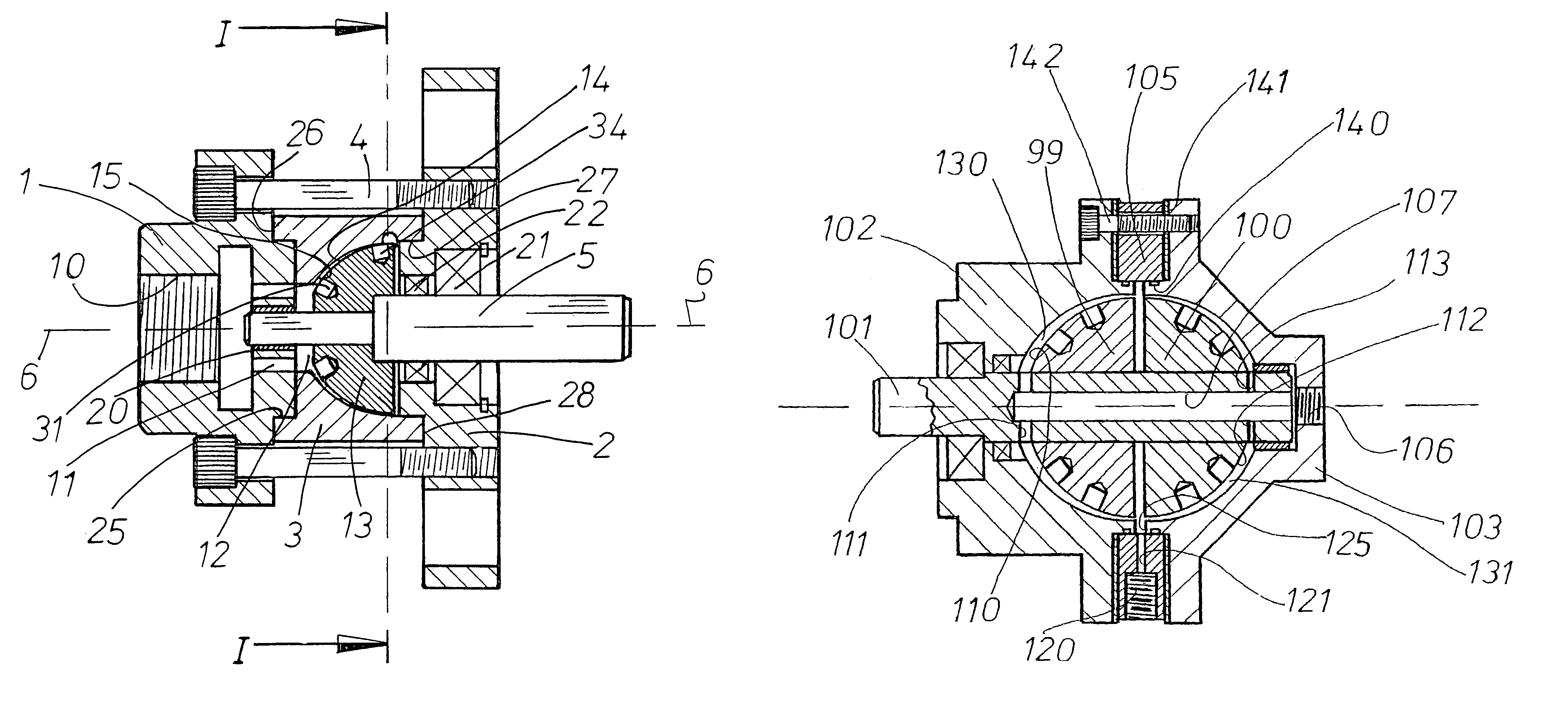
[0044]The device of FIG. 5 employs double hemi-spherical rotors 99, 100, here called a rotor assembly group, where both rotors 99, 100 are preferably driven by a common drive shaft 101 and located inside a housing structure comprising front and rear housing elements 102, 103, and a centrally located sandwich plate 105. The hemi-spherical rotors 99, 100 effectively divide the interior chamber formed by the housing into sub-chambers. Fluid enters the device at inlet 106 and travels through longitudinal hole 107 in drive shaft 101 towards the smaller diameter front-ends 110, 112 of respective rotors 99, 100 by means of respective radial drillings 111, 113 in drive shaft 101. Sandwich plate 105 is provided with fluid exit 120 and passage 121 which communicates with the interior space denoted as 125 which lies radially outwards of rotors 99, 100 and radially inwards of the bore of sandwich plate 105. Fluid entering respective fluid passage gap regions...

fourth embodiment

DETAILED DESCRIPTION OF THE INVENTION

[0045]As the device of FIGS. 6 and 7 differs in two main respects from the third embodiment, it is only necessary to describe the important differences.

[0046]In this example, the rotor and drive shaft are combined together in one rotational element 150, and where element 150 is provided with a first series of openings 151 over the hemi-spherical shaped portion surface 152 and a second series of openings 153 disposed on end face portion 154. The rotating element 150 is supported by bearings 155, 156 in housing members 157, 158, respectively, and where housings 157, 158 are provided with respective interior surfaces 159, 160 that form an internal chamber 161 occupied by rotatable element 150.

[0047]Fluid entering the device at inlet 165 travels through hole 166 in rotatable element 150, and where respective radial holes 167, 168 direct this fluid to the working clearances of the device, namely the first fluid passage gap region formed between interi...


PUM


Abstract

An apparatus for heating a liquid comprising a housing having an internal chamber and a rotor disposed in said chamber. A drive shaft rotatably supported in the housing and extending into said chamber for imparting mechanical energy to the rotor. The rotor having a generally hemi-spherically shaped form and provided with a series of openings. A fluid intake passage in said housing preferably arranged to be nearer the rotational axis of the rotor and a fluid exit passage preferably positioned radially outwardly of said rotor.

Description

BACKGROUND OF THE INVENTION[0001]The invention relates generally to the heating of liquids, and specifically to those devices wherein rotating elements are employed to generate heat in the liquid passing through them. Devices of this type can be usefully employed in applications requiring a hot water supply, for instance in the home, or by incorporation within a heating system adapted to heat air in a building residence. Furthermore, a cheap portable steam generator could be useful for domestic applications such as the removal of winter salt from the underside of vehicles, or the cleaning of fungal coated paving stones in place of the more erosive method by high-pressure water jet.[0002]Of the various configurations that have been tried in the past, types employing rotors or other rotating members are known, one being the Perkins liquid heating apparatus disclosed in U.S. Pat. No. 4,424,797. Perkins employs a rotating cylindrical rotor inside a static housing and where fluid enterin...

Claims


Application Information

Patent Timeline
Patent Type & Authority Patents(United States)
IPC IPC(8): F22B3/06F24J3/00
CPCF24J3/003F24V40/00
Inventor THOMA, CHRISTIAN HELMUT
Owner THOMA CHRISTIAN HELMUT
Why Eureka
Try Eureka