Ball valve

a technology of ball valve and valve body, which is applied in the direction of multiple-way valve, mechanical equipment, transportation and packaging, etc., can solve the problems of inability to check the discharging state of the steam trap provided on the primary side, and the conventional ball valve lacks the capability of discharging fluid at the entrance,

Inactive Publication Date: 2006-08-15
TLV CO LTD
View PDF37 Cites 26 Cited by
  • Summary
  • Abstract
  • Description
  • Claims
  • Application Information

AI Technical Summary

Problems solved by technology

However, the conventional ball valve lacks the capability of discharging fluid at its entrance from a discharge orifice communicating ambient air different from the entrance and exit, and / or releasing remaining pressure at its exit.
For this reason, it is impossible to check the discharging state of a steam trap provided on the primary side and / or to release remaining pressure on the secondary side.

Method used


Image

  • Ball valve
  • Ball valve
  • Ball valve

Examples


Embodiment Construction

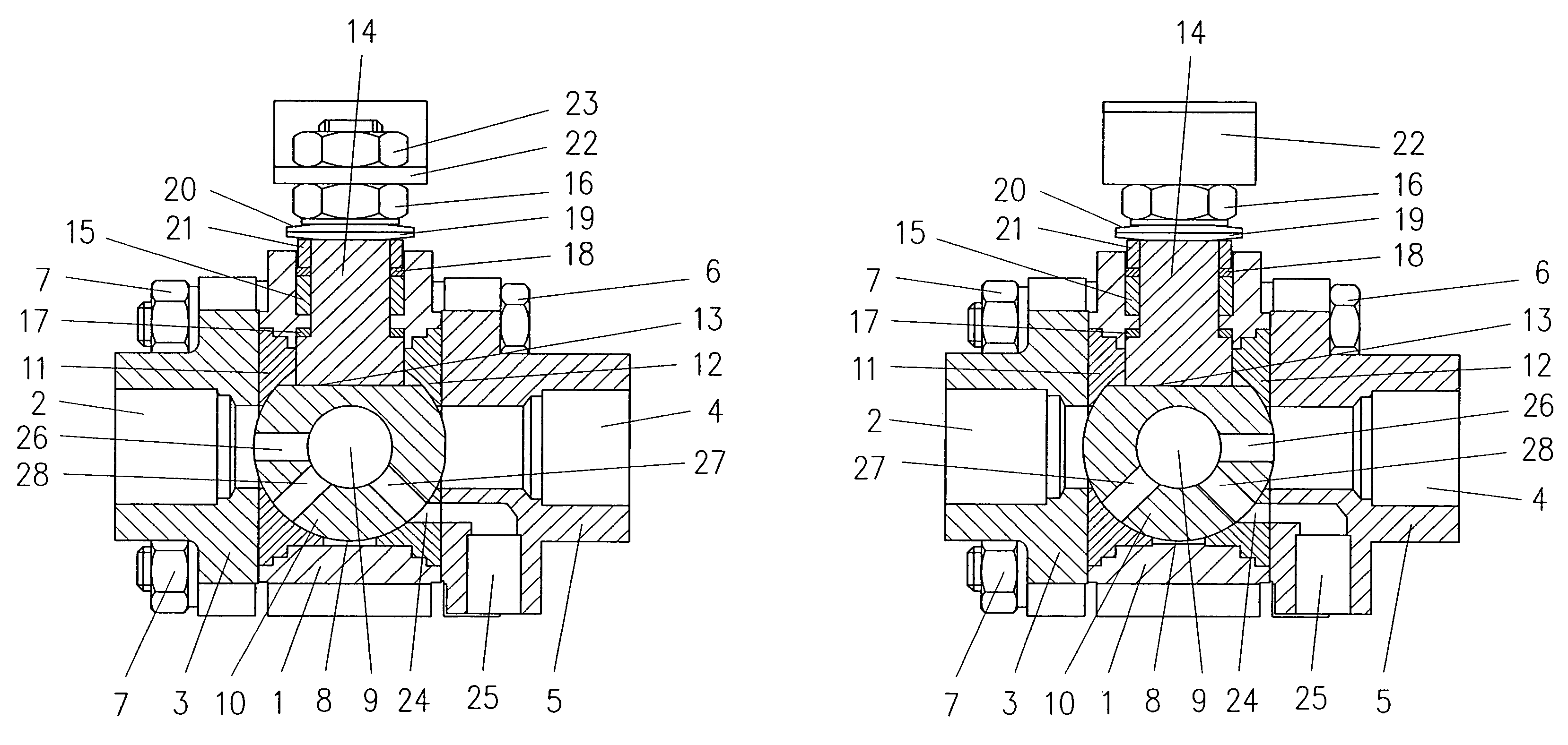
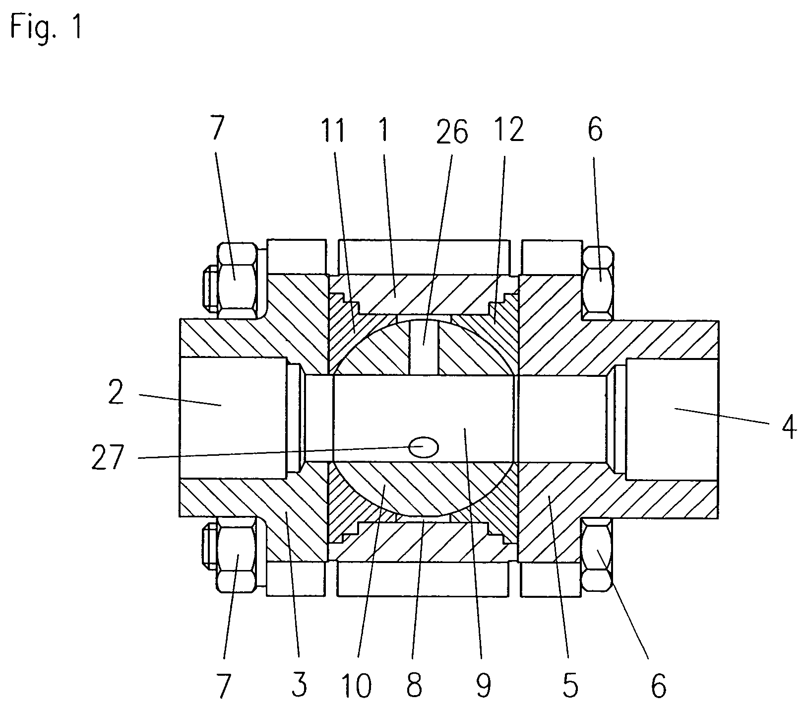
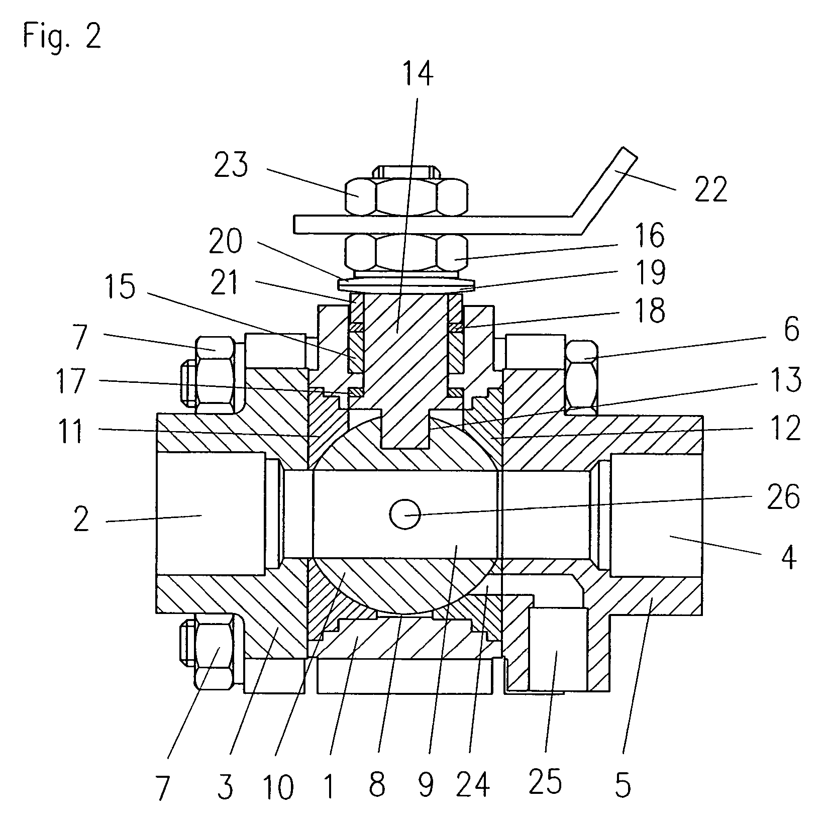
[0039]An example embodiment of the invention is shown in FIGS. 1 to 4. A casing is formed by fastening an entrance side member 3 having an entrance 2 and an exit side member 5 having an exit 4 to a main body 1 with bolts 6 and nuts 7, and a valve chamber 8 where the entrance 2 and the exit 4 communicate with each other is formed in the casing.

[0040]A valve ball 10 where a circulation hole 9 is formed in a straight line in a horizontal direction is rotatably provided in the valve chamber 8. An entrance-side ring valve seat 11 is provided on the entrance 2 side of the valve ball 10, and an exit-side ring valve seat 12 is provided on the exit 4 side of the valve ball 10. The valve ball 10 has a parallel key groove 13 in its upper part, and a key member at a lower end of a valve shaft 14 passing through the main body 1 is engaged with the key groove. The valve shaft 14 holds airtightness with the main body 1 with a packing 15 and is fixed to the main body 1 with nuts 16. Reference numer...


PUM


Abstract

The present invention is a ball valve which may be attached to a fluid pipe for connection / disconnection between an entrance and an exit. More particularly, the present invention is a ball valve having a discharge orifice communicating with ambient air in addition to the entrance and the exit for connection / disconnection between the entrance and the discharge orifice and / or between the exit and the discharge orifice. The ball valve of the present invention may be attached to piping systems such as, for example, the secondary side of a steam trap, which blocks steam but automatically discharges condensed water, and is used for checking a discharging state of the primary side steam trap and / or releasing remaining pressure on the secondary side.

Description

CROSS REFERENCE TO RELATED APPLICATIONS[0001]The present invention claims priority to application Nos. 2003-169317, 2003-169318, and 2003-169319 filed in Japan on Jun. 13, 2003, and Application Nos. 2003-416269, 2003-416270, and 2003-416271 filed in Japan on Dec. 15, 2003 which are expressly incorporated herein in their entirety by reference thereto.FIELD OF INVENTION[0002]The present invention is an improved ball valve which, when placed in a piping system, is capable of discharging fluid outside of the piping system from upstream and / or downstream of the ball valve. A discharge orifice in the ball valve of the present invention communicates with ambient air and can be used to discharge liquid from the entrance or exit of the ball valve while the ball valve is closed and / or may be used to release remaining pressure at the ball valve's exit.BACKGROUND OF THE INVENTION[0003]A conventional ball valve is disclosed in, e.g., Japanese Published Unexamined Utility-Model Application No. Sh...

Claims


Application Information

Patent Timeline
Patent Type & Authority Patents(United States)
IPC IPC(8): B62D5/083F16K5/06F16K11/087F16T1/38
CPCF16K5/0605F16T1/38F16K11/0873Y10T137/86646Y10T137/86871
Inventor MARUTA, TOMONORI
Owner TLV CO LTD
Why Eureka
Try Eureka