Distributed non-combustion type constant-temperature pressurized power generation system

A non-combustion type, power generation system technology, applied in the direction of fuel cell additives, fuel cell components, etc., can solve the problems of commercialization, fossil power pollution, and difficulty in stable control, and achieve system-wide stability Ease of operation, improved thermal efficiency, and stable operation of the entire system achieve the effect

Inactive Publication Date: 2016-08-24
YANGZHOU SANYE NEW ENERGY SCI & TECH CO LTD
View PDF3 Cites 12 Cited by
  • Summary
  • Abstract
  • Description
  • Claims
  • Application Information

AI Technical Summary

Problems solved by technology

Even if pure electric vehicles solve the battery mileage problem, the future charging demand will still have the problem of fossil electricity pollution transfer
[0003] In recent years, hydrogen production technology using liquid fuel and water reforming has become the key breakthrough direction of new energy technology research. According to the research on energy state, the hydrogen produced by the reforming of an equal volume of methanol with water is twice that of an equal volume of liquid hydrogen. Methanology defines methanol as a liquid hydrogen storage material, which has been recognized by the public, and sufficient attention and investment have been paid to the research on hydrogen production technology of alcohols (methanol or ethanol) in the world, but many studies have failed to form commercialization
Mercedes-Benz successfully res

Method used


Image

  • Distributed non-combustion type constant-temperature pressurized power generation system
  • Distributed non-combustion type constant-temperature pressurized power generation system
  • Distributed non-combustion type constant-temperature pressurized power generation system

Examples


example 1

[0032] Example 1, such as figure 1 As shown, at system cold start:

[0033] When the system is cold booted:

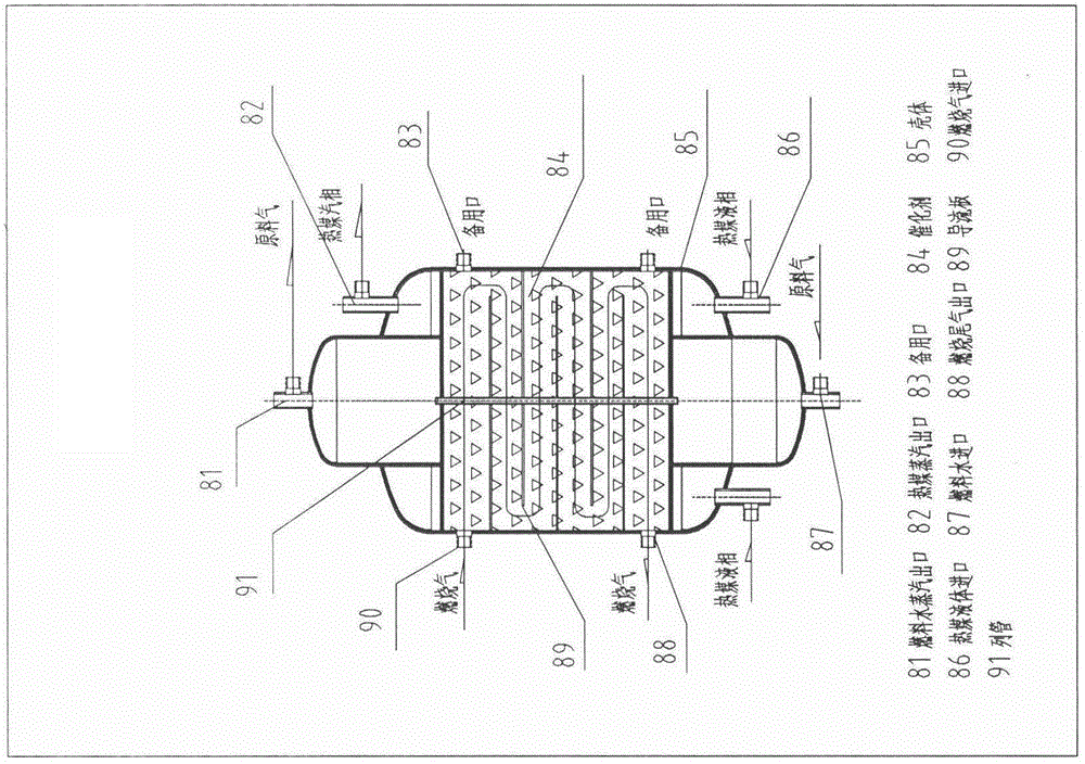
[0034] All valves are controlled to be closed by a system controller (31). Open the valves (42, 43), start the expansion compressor (9), start the fuel atomizer (5) and control the fuel atomization into the mixer B (8) and the hot compressed air mixed into the catalytic combustion reactor (6) pre- Heat the whole system; the catalytic combustion tail gas is discharged from the catalytic combustion reactor (6) through the expansion compressor (9) to recover the heat work and reduce the power consumption of the compressed air before being emptied.

[0035] When the circulating heat medium in the catalytic combustion reactor (6) reaches the control pressure, the system controller (31) opens the valves (46, 49, 53), starts the fuel cell cooling circulation pump (15) and the fuel-water ratio pump (3 ), the fuel-water ratio pump (3) draws water and fuel in a certain ratio ...


PUM


Abstract

The invention provides a distributed non-combustion type constant-temperature pressurized power generation system. The system comprises a water tank (1), a fuel storage tank (2), a fuel water proportioning pump (3), a mixer A (4), a fuel atomizer (5), a second heat exchanger (26), a first heat exchanger (25), dehydration tanks (27, 28 and 12), a carbon monoxide removal reactor (11), a catalytic combustion reactor (6), a fuel water reforming reactor (29), a composite air-cooling heat sink (22), a hydrogen-air pressure balancer (14), a fuel cell cooling liquid tank (13), a compressed air heat exchanger (23), a fuel cell cooling circulation pump (15), a recycled hydrogen compressor (21), a hydrogen-rich storage tank (19), a hydrogen recycle membrane separator (17), a hydrogen fuel cell pack (16), an exhaust purifier (7), an expansion compressor (9), a control valve (18), a (normal-pressure fuel water) vapor-liquid separator (20), a mixer B (8), a mixer C (10), a mixer D (24), a steam trap (30), a system controller (31), a one-way valve (41) and valves (42-54). By applying an energy state theory, a vapor-liquid two-phase coexistence constant-temperature condensation or evaporation principle and phase-change heat-transfer highest efficiency principle, hydrogen production by reforming and constant-temperature control on a hydrogen fuel battery are achieved.

Description

technical field [0001] The invention relates to the fields of new energy power generation, renewable energy power generation, clean energy power generation, hydrogen fuel cell power generation and the like. In particular, hydrogen fuel cell vehicles have been developed for many years and have not been widely used. There are two bottlenecks: one is that the storage and transportation of hydrogen sources has always made hydrogen uneconomical; the other is the price of hydrogen fuel cells. The high cost and short lifespan make it difficult to commercialize hydrogen fuel cells. Although many researchers have used reforming technology to reform liquid fuel and water to produce hydrogen to achieve distributed or mobile hydrogen production, the stability of the reforming hydrogen production system has not been well resolved. Reforming hydrogen generation technology has not been commercialized. According to the theory of energy states, the use of liquid fuel and water reforming to p...

Claims


Application Information

Patent Timeline
IPC IPC(8): H01M8/04H01M8/02
CPCY02E60/50
Inventor 邵天明胡振民
Owner YANGZHOU SANYE NEW ENERGY SCI & TECH CO LTD
Why Eureka
Try Eureka