Surround sound positioning tower system and method

a positioning tower and sound system technology, applied in the direction of casings/cabinets/drawers, cabinet details, casings/cabinets/drawers, etc., can solve the problems of not being able to facilitate human factors, not being able to adapt to the use of the average electronics consumer, and the current art laser-based alignment tool does not allow for flexibility of room geometry, so as to facilitate customizing and/or optimizing sound direction and constructive interference patterns, the effect of optimizing

Active Publication Date: 2006-08-15
MONSTER
View PDF27 Cites 48 Cited by
  • Summary
  • Abstract
  • Description
  • Claims
  • Application Information

AI Technical Summary

Benefits of technology

[0003]The present invention surround sound system and method addresses the current need for a surround sound positioning tower system and method having a positioning feature for customizing sound direction and constructive interference patterns by the average electronics consumer, especially in a home theater. The present invention system comprises consistent geometric alignment of a multi-channel sound system and may be integrated into any type of speaker system. The present invention surround sound system may comprise: a surround sound tower being vertically disposed; a base plate being horizontally disposed; and a structure for positioning the surround sound tower on the base plate, the surround sound tower being mounted on, and normal to, the positioning structure, wherein the positioning structure may comprise: a structure for indicating an angular rotation of the surround sound tower relative to the base plate; and a structure for facilitating rotation of the angular rotation indicating structure, wherein the angular rotation indicating structure may comprise a pointer plate having a visible marking, e.g., a dial, and wherein the facilitating structure may comprise a plurality of ball bearings, and wherein the base plate may comprise a plurality of angular indications, e.g., reference center points and calibrated angular indications for precisely orienting or positioning the tower, wherein the surround sound tower may comprise at least one feature selected from a group consisting essentially of a center channel speaker, and a tweeter module, wherein the tweeter module may comprise: a tweeter; and a detachable permeable tweeter housing disposed around the tweeter. The present invention system may further comprise a binding post disposed at a rear surface of the tower for both electronically and mechanically binding the tower to the positioning structure; and may further comprise a structure for indicating a sonic intensity, wherein the sonic intensity indicating structure may comprise a light pipe. Such light pipe may be disposed on a rear side of the tower for producing a aura visual effect when viewed from a front side.
[0004]At least one surround sound system may be simply configured in a home theater environment for customizing sound direction and constructive interference patterns by the average electronics consumer, because each system comprises its own positioning structure, whereby repeatability is provided for any given prior positioning selection in the event that the at least one system becomes disoriented, e.g., by a seismic event. The present invention system may further comprise simulation software for generating precise geometric data; and electro-mechanical actuators, receiving the generated data, for facilitating customizing and/or optimizing sound direc

Problems solved by technology

Other current art home theater systems comprise highly specialized installation/orientation features which require extensive technical training and are, thus, not well-suited for

Method used


Image

  • Surround sound positioning tower system and method
  • Surround sound positioning tower system and method
  • Surround sound positioning tower system and method

Examples


Embodiment Construction

,” disclosed, infra.

BRIEF DESCRIPTION OF THE DRAWING(S)

[0008]For a better understanding of the present invention, reference is made to the below referenced accompanying Drawing(s). Reference numbers refer to the same or equivalent parts of the present invention throughout the several figures of the Drawing(s).

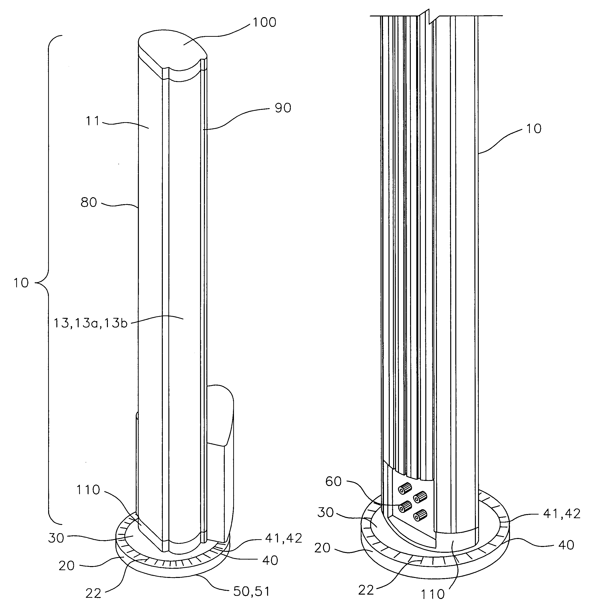
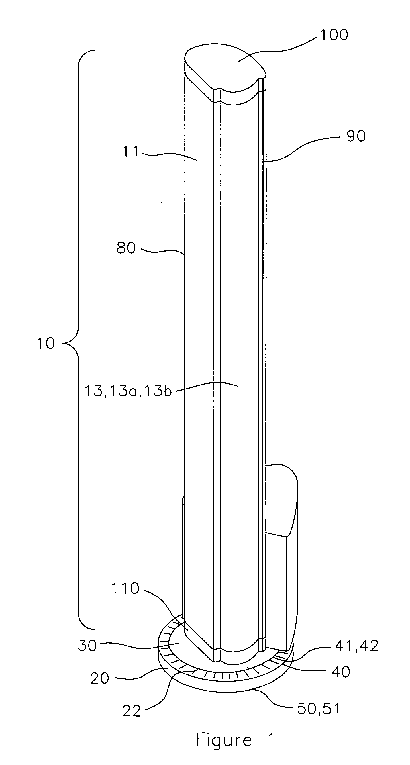
[0009]FIG. 1 is a perspective view of a surround sound system comprising: a surround sound tower being vertically disposed; a base plate being horizontally disposed; and a structure for angularly positioning the surround sound tower on the base plate, the surround sound tower being mounted on, and normal to, the angularly positioning structure, wherein the angularly positioning structure may comprise: a structure for indicating an angular rotation of the surround sound tower relative to the base plate; and a structure for facilitating rotation of the angular rotation indicating structure, in accordance with the present invention.

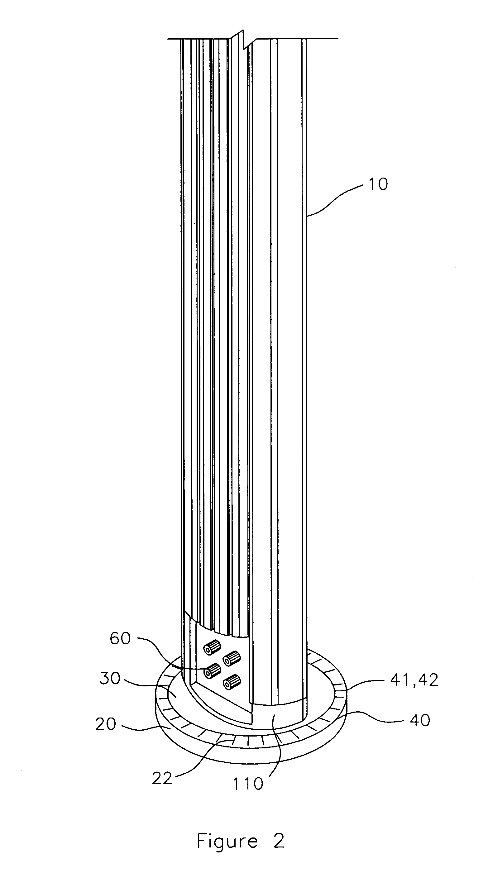
[0010]FIG. 2 is a rearward perspective view of a ...


PUM


Abstract

A surround sound system and method involving a surround sound tower; a base plate; and a structure for positioning the surround sound tower on the base plate, the surround sound tower being mounted on, and normal to, the positioning structure for customizing sound direction and constructive interference patterns by interactively positioning the sound tower and/or at least one sound tower and by modular usage of tweeters, economizing floor space, especially in a home theater environment. The positioning structure may have a structure for indicating an angular rotation of the surround sound tower relative to the base plate and a structure for facilitating rotation of the angular rotation indicating structure.

Description

TECHNICAL FIELD[0001]The present invention relates to surround sound systems and methods. More particularly, the present invention relates to surround sound tower systems and methods. Even more particularly, the present invention relates to surround sound positioning tower systems and methods.BACKGROUND ART[0002]Installing a home theater system which recreates the acoustic experience of any given soundtrack is vital to meeting the electronic consumer's expectations. Current art home theater surround sound systems typically comprise compact disc / digital video disc (CD / DVD) players and / or changers, audio / visual (A / V) receivers, tuners, equalizers, headphones, satellite speakers, center channel speakers, woofers, and / or subwoofers disposed in a fixedly mounted rectanguloid housing. Other current art home theater systems comprise highly specialized installation / orientation features which require extensive technical training and are, thus, not well-suited for use by the average electroni...

Claims


Application Information

Patent Timeline
IPC IPC(8): A47B81/06H04R1/02H04R5/02H05K5/02H04R9/06H04S3/00H04S7/00
CPCH04R1/026H04R5/02
Inventor LEE, NOELMARTIN, DEMIAN
Owner MONSTER
Why Eureka
Try Eureka