Electromagnetic coaxial driving injection apparatus

Inactive Publication Date: 2006-08-15
IND TECH RES INST
View PDF7 Cites 7 Cited by
  • Summary
  • Abstract
  • Description
  • Claims
  • Application Information

AI Technical Summary

Benefits of technology

[0013]The present invention is based on the reducing of systematic inertia and friction, providing a novel magnetic coaxial injection apparatus. In the prime driving force, we use a newly designed linear driving apparatus (including more than one liner motor) and rotational driving apparatus, to provide a driving force respectively for injection and metering. The moving parts of both form a common axis with the injectional

Problems solved by technology

However, due to the compressibility behavior of fluid and change of properties thereof with temperature, positioning accuracy is comparatively poor.
Furthermore, noise is generated during operation, cleaning is difficult and power consumption is high.
Therefore, a complicated mechanism of belt and pulleys is required.
This causes the structure to be complicated and requirement for space to be high.
Therefore, the injection driving motor not only drives the injection screw and a plastics melting device, but also the met

Method used


Image

  • Electromagnetic coaxial driving injection apparatus
  • Electromagnetic coaxial driving injection apparatus
  • Electromagnetic coaxial driving injection apparatus

Examples


Embodiment Construction

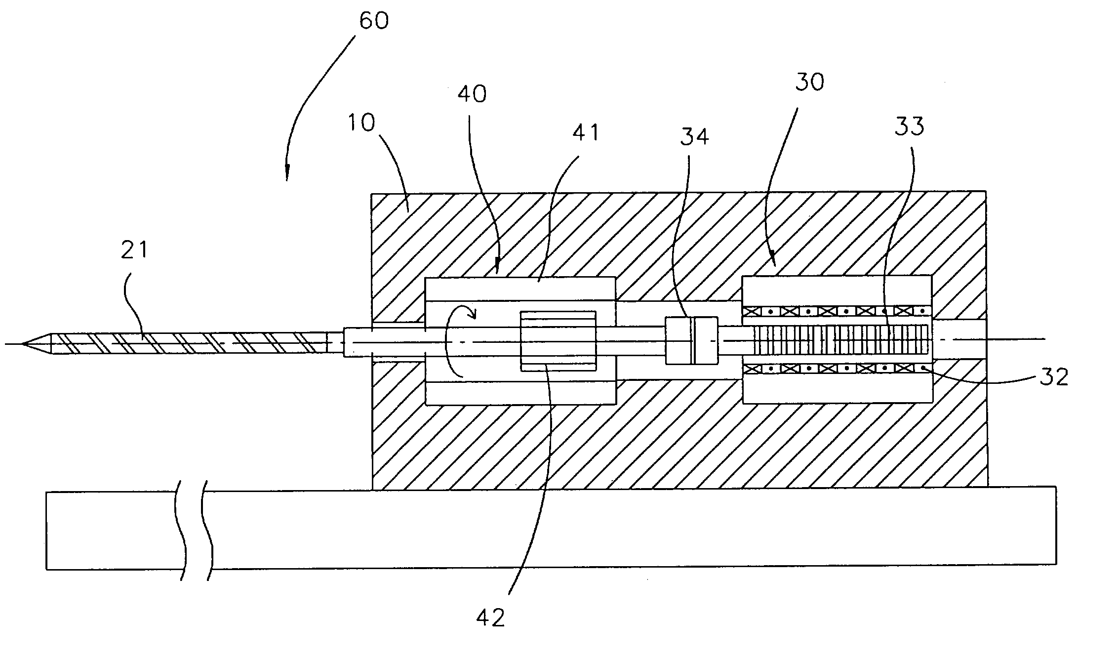
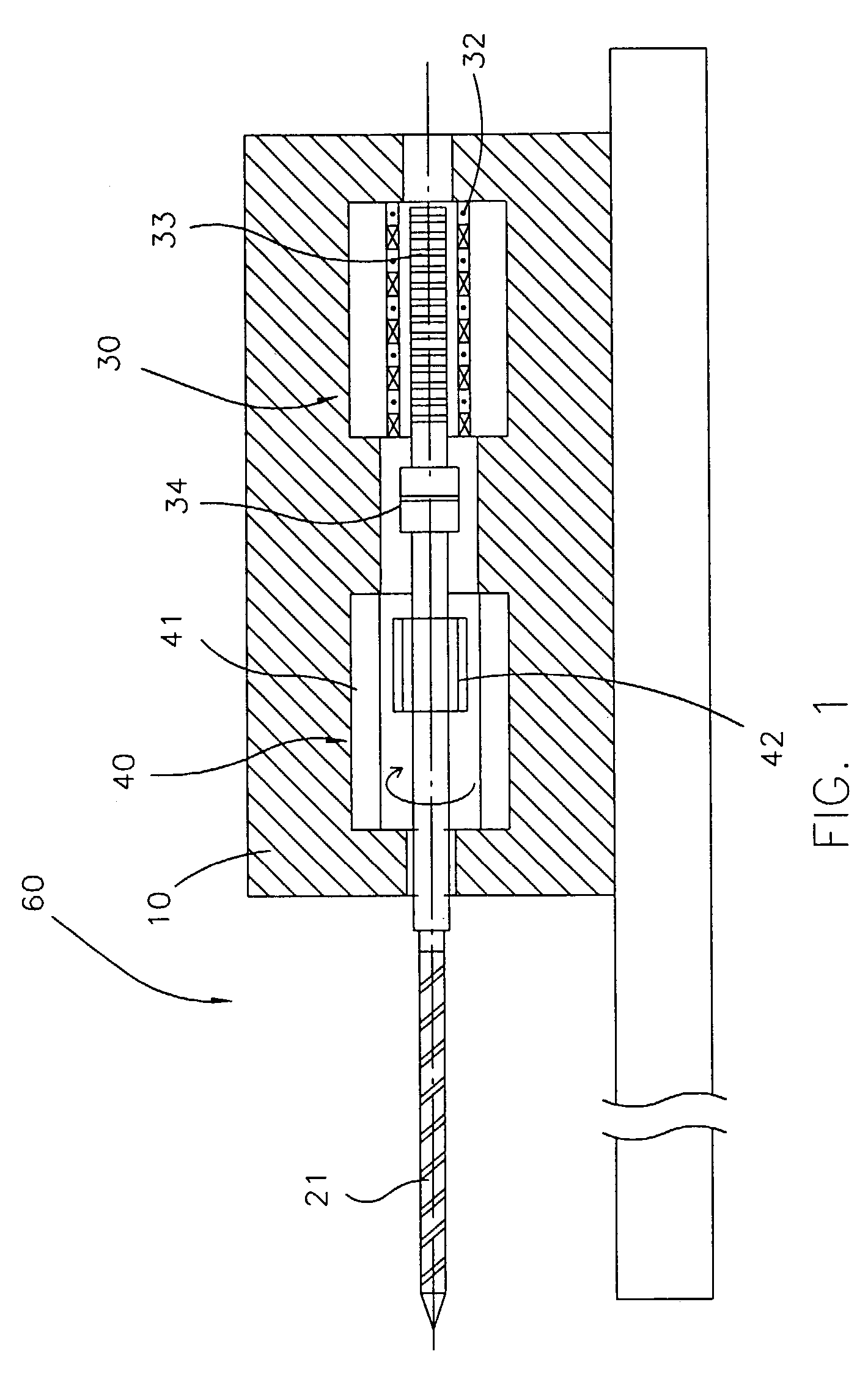
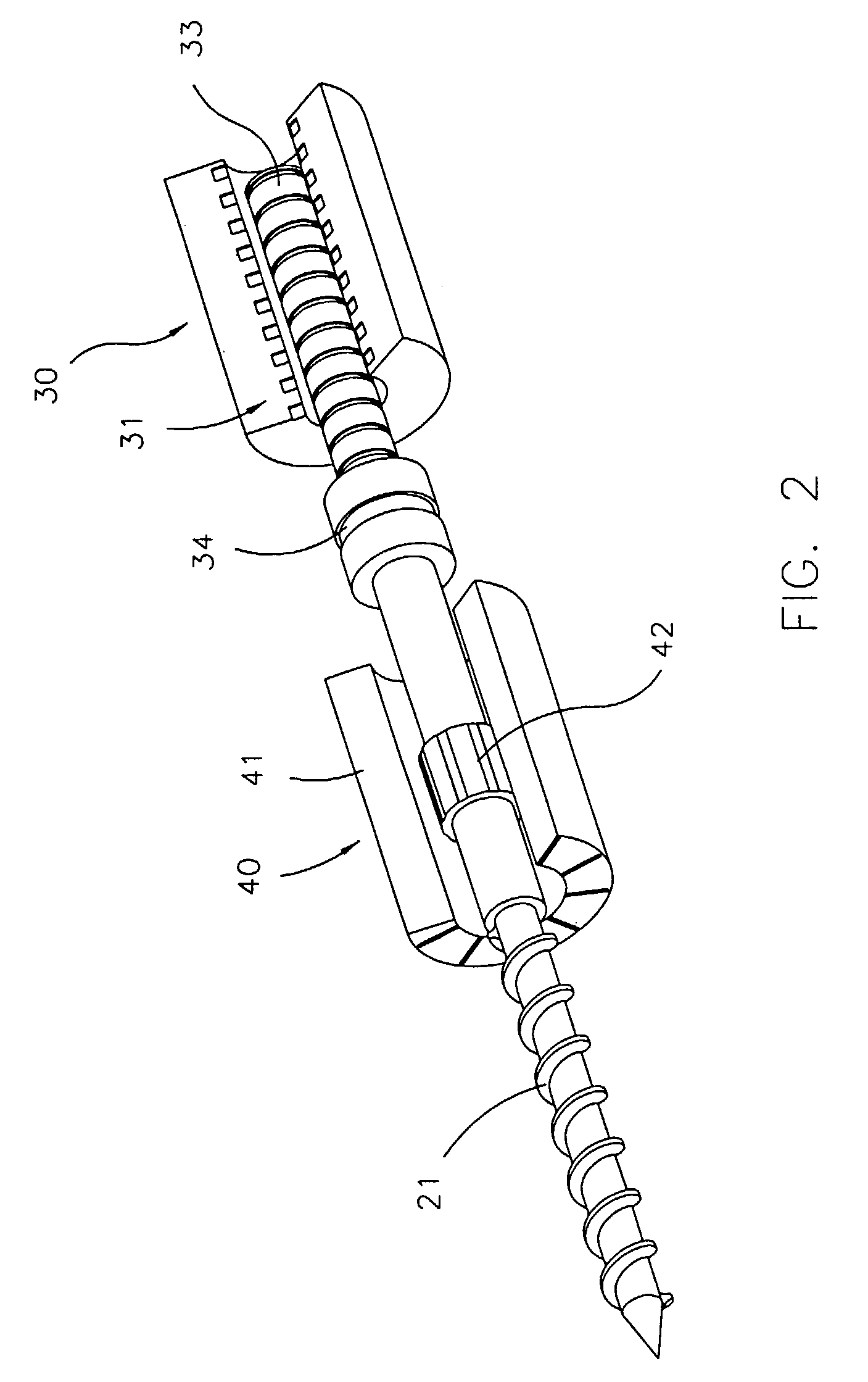
[0020]As shown in FIGS. 1 and 2, the electromagnetic coaxial driving injection apparatus of the present invention mainly comprises: a frame 10; an injection screw 21; an injection driving device 30; and a metering driving device 40. The injection screw 21 has a screwed part and an unscrewed part that form a single body or two distinct bodies.

[0021]The injection driving device 30 drives the injection screw 21 to perform a linear injection movement on a common axis. In the embodiment shown the injection driving device 30 is a linear motor having a stator 31, constituting a fixed part, and a rotor 33 which is linearly movable. The injection stator 31 forms a tube, mounted inside the frame 10, a front end thereof being connected with the injection screw 21 via a connecting device 34. Alternatively, a connection is established by threads or a single body is formed. The injection rotor 33 and the injection screw 21 share a common symmetry axis.

[0022]Referring to FIG. 4, in the embodiment ...


PUM

PropertyMeasurementUnit
Lengthaaaaaaaaaa
Magnetic fieldaaaaaaaaaa
Transmissionaaaaaaaaaa

Abstract

An electromagnetic coaxial driving injection apparatus, having a linear motor for driving injection and a rotation motor for metering. The linear motor and the rotation motor of both the injection and metering motors and an injection screw are set on a common axis. A connecting device connects moving parts of the motors with the injection screw. Stationary parts of the motors are fastened on a frame and forward-backward moving unit, not moving during injection and metering. Due to the arrangement of the moving parts and the injection screw on a single axis, moving parts are lessened, and transmission losses are minimized. Since the number of structural parts is low, only the moving parts of the motors move during injection while the stationary parts thereof remain at rest, thus greatly reducing inertia. Furthermore, since the moving axis of the injection screw and the injection screw are linked, without being connected with stators or other structural parts, injection is performed with minimal friction, enhancing effectiveness of the apparatus.
The main characteristic of the present invention is that, due to direct driving of injection without mechanical transmission, the effects of hysteresis and backlash are avoided. Furthermore, inertia and friction are reduced. The present invention increases the response and reappearance of the system.

Description

BACKGROUND OF THE INVENTION[0001]With steady technological progress, demands on precision of molding are increasing by the day. Of particular importance are speed and aiming precision of injection molding machines. Previously, injection pressure was generated by hydraulic devices or servomotors. Mechanic transmission, however, effects hysteresis and backlash, so that injection is not aimed precisely and demands of high technology are not met. During metering, the driving unit of the injection screw moves along with the injection driving device, greatly increasing inertia. In addition, the accuracies at the end of movement is reduced, thereby reducing the precision in molding. Thus, the present invention developed to eliminate the positional inaccuracies and injectional backlash generated by mechanic transmission and high inertia, thereby achieving high speed and precision molding.[0002]1. Basic Object of the Present Invention[0003]An electromagnetic coaxial driving injection apparat...

Claims


Application Information

Patent Timeline
IPC IPC(8): B29C45/50B29C45/46
CPCB29C45/5008B29C2045/504B29C2045/5024B29C2045/1793
Inventor HSU, CHIA-CHUNCHUNG, YONG-CHENLIN, CHIA-HUNGFENG, WEN-HUNGCHEN, MING-CHI
Owner IND TECH RES INST
Why Eureka
Try Eureka