
Method of manufacturing a semiconductor light emitting device, semiconductor light emitting device, method of manufacturing a semiconductor device, semiconductor device, method of manufacturing a device, and device

a technology of light-emitting devices and semiconductors, which is applied in the direction of semiconductor lasers, crystal growth processes, polycrystalline materials, etc., can solve the problems of deteriorating device properties, difficult to obtain substrates with defect reduction, and semiconductors obtained by growth exhibit very high defect densities, etc., to achieve the effect of improving property

Inactive Publication Date: 2006-08-15
SONY CORP +1
View PDF22 Cites 12 Cited by
  • Summary
  • Abstract
  • Description
  • Claims
  • Application Information

AI Technical Summary

Benefits of technology

[0010]It is therefore an object of the invention to provide a semiconductor light emitting device excellent in property such as emission property, reliable and elongated in lifetime, as well as a method capable of manufacturing such a semiconductor light emitting device.
[0028]The border lines of each device region are determined to use the given area of the substrate efficiently, depending upon the layout pattern of the second regions, or their interval or period, to the extent ensuring that no device region includes the second regions substantially. Typically, the border lines of each device region are determined to include a straight line connecting at least two adjacent second regions. In the dicing process for separation into chips, the nitride III–V compound semiconductor substrate having nitride III–V compound semiconductor layers grown thereon is preferably diced along such border lines each including the straight line connecting at least two adjacent second regions. The dicing typically relies on cleavage, but other methods using a diamond saw or a laser beam may be used alternatively for the same purpose. Especially when cleavage is employed as the dicing, the border lines of each device region, which includes a straight line connecting at least two adjacent second regions, facilitates desirable cleavage, because the second regions having an average dislocation density higher than that of the first region is weaker in mechanical strength than the first region. This is especially advantageous for obtaining desirable cavity edges of semiconductor lasers. The border lines of each device region may be determined not to pass any second regions. In this case, the border lines of each device region should preferably be distant from the second regions by at least 1 μm in order to minimize adverse influences of the second regions. Thus, in the dicing process, the nitride III–V compound semiconductor substrate having nitride III–V compound semiconductor layers grown thereon is diced along the border lines distant inside from the second regions.

Problems solved by technology

This is because defects of substrates are copied to semiconductor layers growing thereon and often invite deterioration of device properties.
However, nitride III–V compound semiconductors are difficult to form by bulk growth, and it has been difficult to obtain substrates reduced in defect to a level acceptable for use as substrates of semiconductor devices.
However, even through that process, nitride III–V compound semiconductors obtained by growth exhibit very high defect densities, and give considerable influences to device properties.
Moreover, it is out of control where the high defect density regions appear, and they appear at random.
Therefore, in case a semiconductor device, such as a semiconductor laser, is manufactured by growth of nitride III–V compound semiconductor layers on the single-crystal GaN substrate, this technique cannot prevent a high defect density region from being formed in the emission region, and inevitably invites degradation of emission properties and reliability of semiconductor lasers.

Method used


Image

  • Method of manufacturing a semiconductor light emitting device, semiconductor light emitting device, method of manufacturing a semiconductor device, semiconductor device, method of manufacturing a device, and device
  • Method of manufacturing a semiconductor light emitting device, semiconductor light emitting device, method of manufacturing a semiconductor device, semiconductor device, method of manufacturing a device, and device
  • Method of manufacturing a semiconductor light emitting device, semiconductor light emitting device, method of manufacturing a semiconductor device, semiconductor device, method of manufacturing a device, and device

Examples


first embodiment

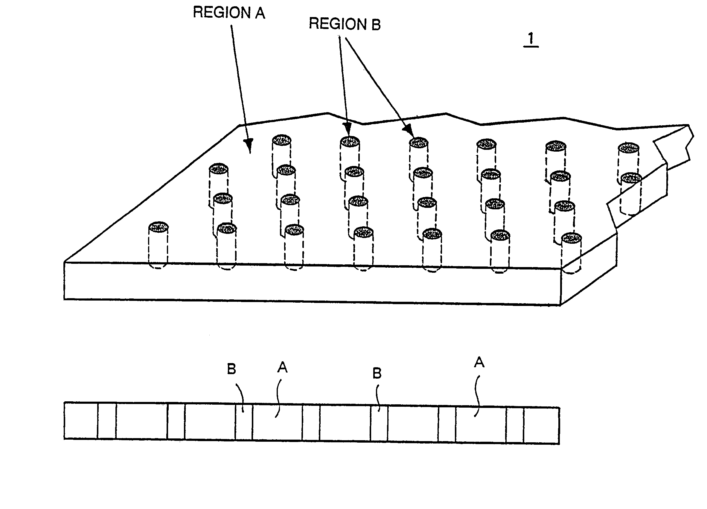
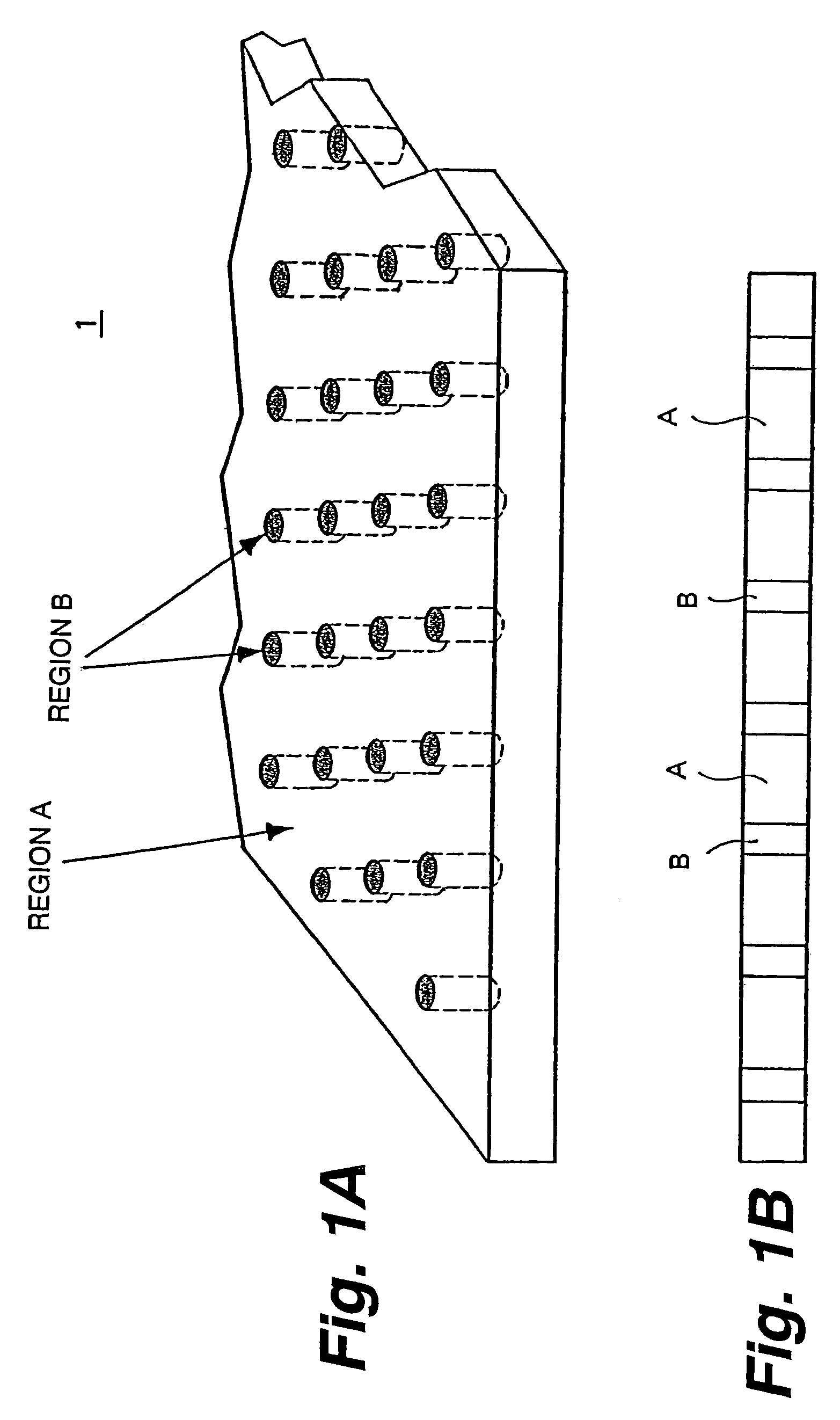
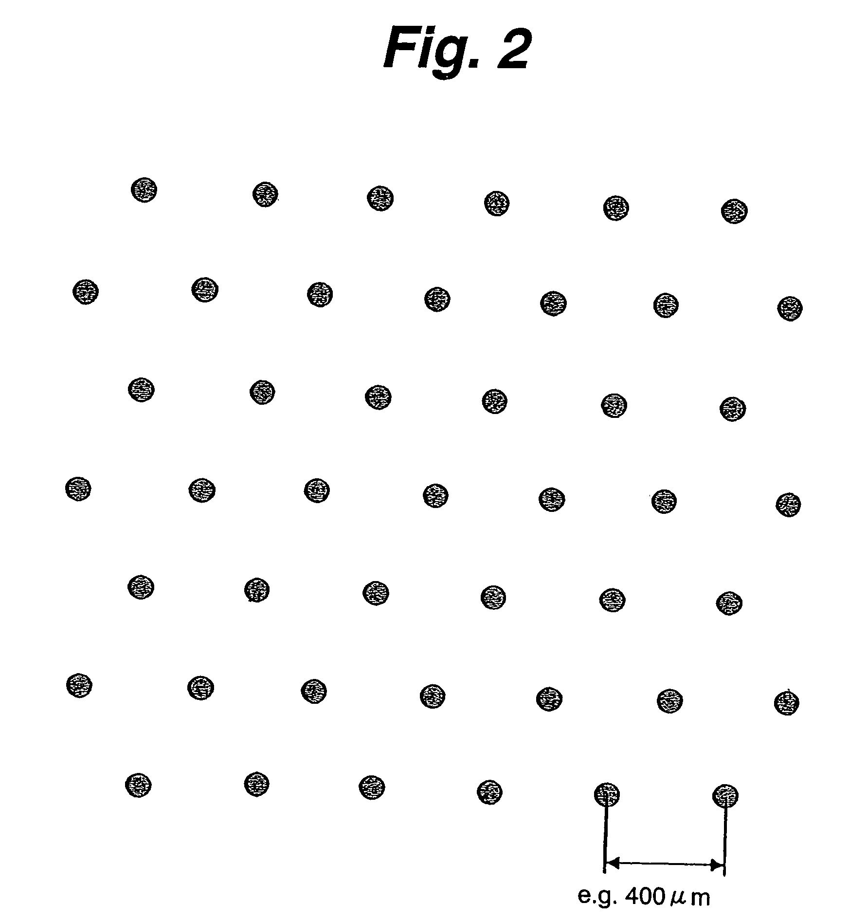
[0176]FIG. 6 is a plan view showing the GaN substrate used in the Perspective and cross-sectional views of the GaN substrate 1 appear as shown in FIGS. 1A and 1B. The GaN substrate 1 is an n-type substrate having a (0001) plane (C-plane) orientation. The GaN substrate 1, however, may be of an R-plane, A-plane or M-plane orientation. In the GaN substrate 1, regions B composed of a crystal having a high average dislocation density periodically align in form of hexagonal lattices in the region A having a low average dislocation density. In this case, the straight line connecting nearest two regions B coincides with the orientation of GaN or its equivalent. Alternatively, the straight line connecting nearest two regions B may coincide with the orientation or its equivalent of GaN. The regions B penetrate the GaN substrate 1. Thickness of the GaN substrate 1 is 200˜600 μm, for example. Broken lines in FIG. 6 are shown only for demonstrating relative positional relations among the regi...

second embodiment

[0211]Next explained is the invention.

[0212]As shown in FIG. 12, in the second embodiment, both the shorter sides and the longer sides of the rectangular device region 2, which form border lines of each device region 2, are straight lines connecting centers of regions B unlike the first embodiment. Here again, the laser stripes 3 lie on lines connecting midpoints of shorter sides of individual device regions 2. In this manner, transfer of influence of the regions B to the emission regions can be prevented.

[0213]The second embodiment is different from the first embodiment in forming cavity mirrors by dicing the substrate by cleavage along the border lines of the device regions 2 that are straight lines connecting centers of regions B.

[0214]The regions B having more dislocations are considered easier to break than the region A. Therefore, when the substrate is diced along the straight lines that connect regions B, the regions B function as perforation, and the region A is clearly clea...

third embodiment

[0218]Next explained is the invention.

[0219]In the third embodiment, as shown in FIG. 14, regions B made of a crystal having a higher average dislocation density are aligned periodically in form of rectangular lattices in the region A having a lower average dislocation density in a GaN substrate 1. A single rectangle having regions B at its four corners is defined as a single device region 2. In this case, each straight line connecting nearest two adjacent regions B in the lengthwise direction of the rectangle coincides with the orientation of GaN, and each straight line connecting nearest two adjacent regions B and being one of shorter side of the rectangle coincides with the orientation of GaN.

[0220]Interval of regions B in the lengthwise direction of the rectangular lattices is 600 μm, for example, and interval of regions B in the direction parallel to the shorter sides of the rectangular lattices is 400 μm, for example. In this case, each device region 2 is sized 600×400 μm.

[0...


PUM

PropertyMeasurementUnit
Diameteraaaaaaaaaa
Diameteraaaaaaaaaa
diameteraaaaaaaaaa

Abstract

When a semiconductor light emitting device or a semiconductor device is manufactured by growing nitride III–V compound semiconductor layers, which will form a light emitting device structure or a device structure, on a nitride III–V compound semiconductor substrate composed of a first region in form of a crystal having a first average dislocation density and a plurality of second regions having a second average dislocation density higher than the first average dislocation density and periodically aligned in the first region, device regions are defined on the nitride III–V compound semiconductor substrate such that the device regions do not substantially include second regions, emission regions or active regions of devices finally obtained do not include second regions.

Description

RELATED APPLICATION DATA[0001]This application is a divisional of co-pending application Ser. No. 10 / 719,206 filed Nov. 21, 2003, which is a continuation of PCT application No. PCT / JP02 / 10323 filed Oct. 3, 2002. The present and foregoing applications claim priority to Japanese Application No. P2001-315703 filed Oct. 12, 2001. Each of these applications is incorporated herein by reference to the extent permitted by law.[0002]This invention relates to a method of manufacturing a semiconductor light emitting device, a semiconductor light emitting device, method of manufacturing a semiconductor device, a semiconductor device, a method of manufacturing a device, and a device itself, that are suitable for use in the manufacture of semiconductor lasers, light emitting diodes or electron transport devices composed of nitride III–V compound semiconductors, for example.[0003]Widely used conventional methods for manufacturing semiconductor devices first grow desired semiconductor layers on app...

Claims


Application Information

Patent Timeline
Patent Type & Authority Patents(United States)
IPC IPC(8): H01L21/00C30B25/02H01L21/20H01L33/00H01L33/02H01L33/16H01L33/32H01S5/02H01S5/20H01S5/22H01S5/223H01S5/323H01S5/40
CPCB82Y20/00C30B29/403C30B29/406H01L33/007H01L33/0095H01L33/025H01S5/32341H01S5/34333C30B25/02H01S2301/173H01L21/0254H01L21/0262H01L21/02664H01L33/32H01S5/0207H01S5/0213H01S5/2036H01S5/22H01S5/2201H01S5/2231H01S5/4031
Inventor ASATSUMA, TSUNENORITOMIYA, SHIGETAKATAMAMURA, KOSHITOJO, TSUYOSHIGOTO, OSAMUMOTOKI, KENSAKU
Owner SONY CORP
Learn More