Radiation protection system

a radiation protection system and radiation protection technology, applied in the field of radiation protection systems, can solve the problems of medical personnel still exposed to radiation, adverse effects, and exposure to radiation by such personnel

Inactive Publication Date: 2006-08-15
ECO CATH LAB SYST +1
View PDF51 Cites 18 Cited by
  • Summary
  • Abstract
  • Description
  • Claims
  • Application Information

AI Technical Summary

Benefits of technology

[0009]In one aspect, a method is provided of performing a medical procedure. The method includes providing a radiation-shielding cubicle having an interior defining a medical personnel region and including a first wall having an opening therein, locating the cubicle with respect to an x-ray table so a portion of the x-ray table extends through the opening into the interior of the cubicle, and separating medical personnel from an x-ray emitter disposed outside of the cubicle using the first wall to shield the medical personnel from radiation emitted by the x-ray emitter.
[0011]In even another aspect, a method is provided of performing a medical procedure. The method includes providing a radiation-shielding wall having an opening therein, locating the wall with respect to an x-ray table so a portion of the x-ray table extends through the opening, joining the x-ray table to the wall using a radiation-shielding flexible interface, sealing the opening in the first wall using a flexible radiation-resistant skirt, and using the wall to separate medical personnel located adjacent a first side of the wall from an x-ray emitter disposed adjacent a second side of the wall opposite the first side to shield the medical personnel from radiation emitted by the x-ray emitter.

Problems solved by technology

X-rays are used in a wide variety of medical procedures, many of which require medical personnel to be in direct contact with the patient, thereby exposing such personnel to radiation.
However, operators and health care personnel performing numerous procedures per year over many years may be exposed to significant cumulative radiation doses over time, which may have adverse effects.
Despite the use of these shields, medical personnel are still exposed to radiation.
This long term, cumulative exposure may cause adverse effects.
Furthermore, the wearing of heavy lead aprons may have long term deleterious effects resulting in disabling disorders of the spine in a significant number of operators.
Though there are numerous shapes and designs for these shields, and although they may be constructed of various materials, they do not sufficiently protect against radiation exposure, and medical personnel must still wear heavy and encumbering leaded protective clothing.
Furthermore, such leaded protective aprons, collars and glasses do not fully protect the operator as they leave substantial portions of legs, arm and head exposed.
Despite dramatic technological evolution of the imaging systems employed for diagnostic and therapeutic radiological procedures, the fundamental architecture of the radiological x-ray laboratory and its ancillary components have not changed appreciably over the last 50 years.
However, in order to perform diagnostic and therapeutic procedures, such a laboratory requires multiple other capital equipment items, as well as disposables.

Method used


Image

  • Radiation protection system
  • Radiation protection system
  • Radiation protection system

Examples


second embodiment

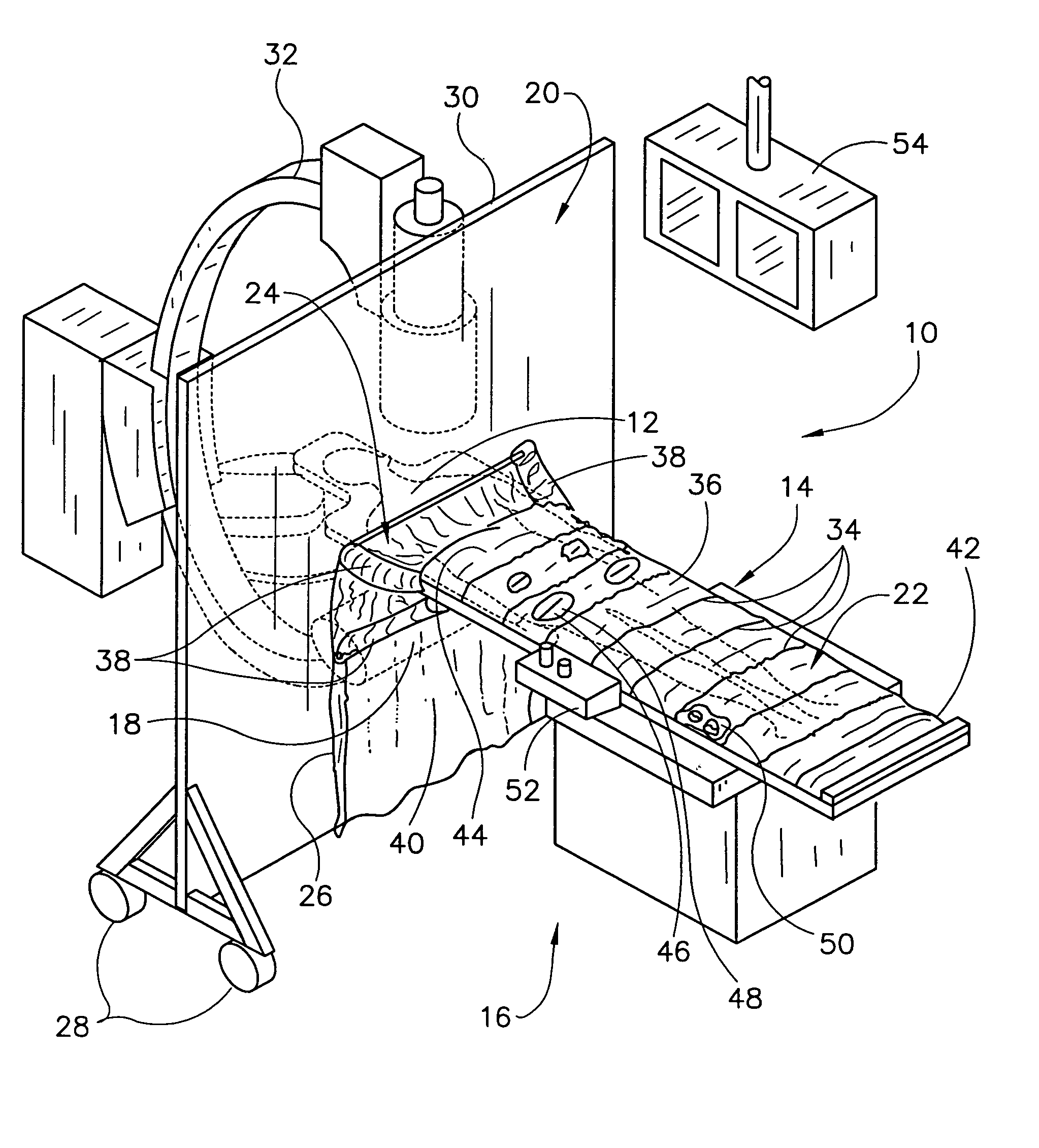
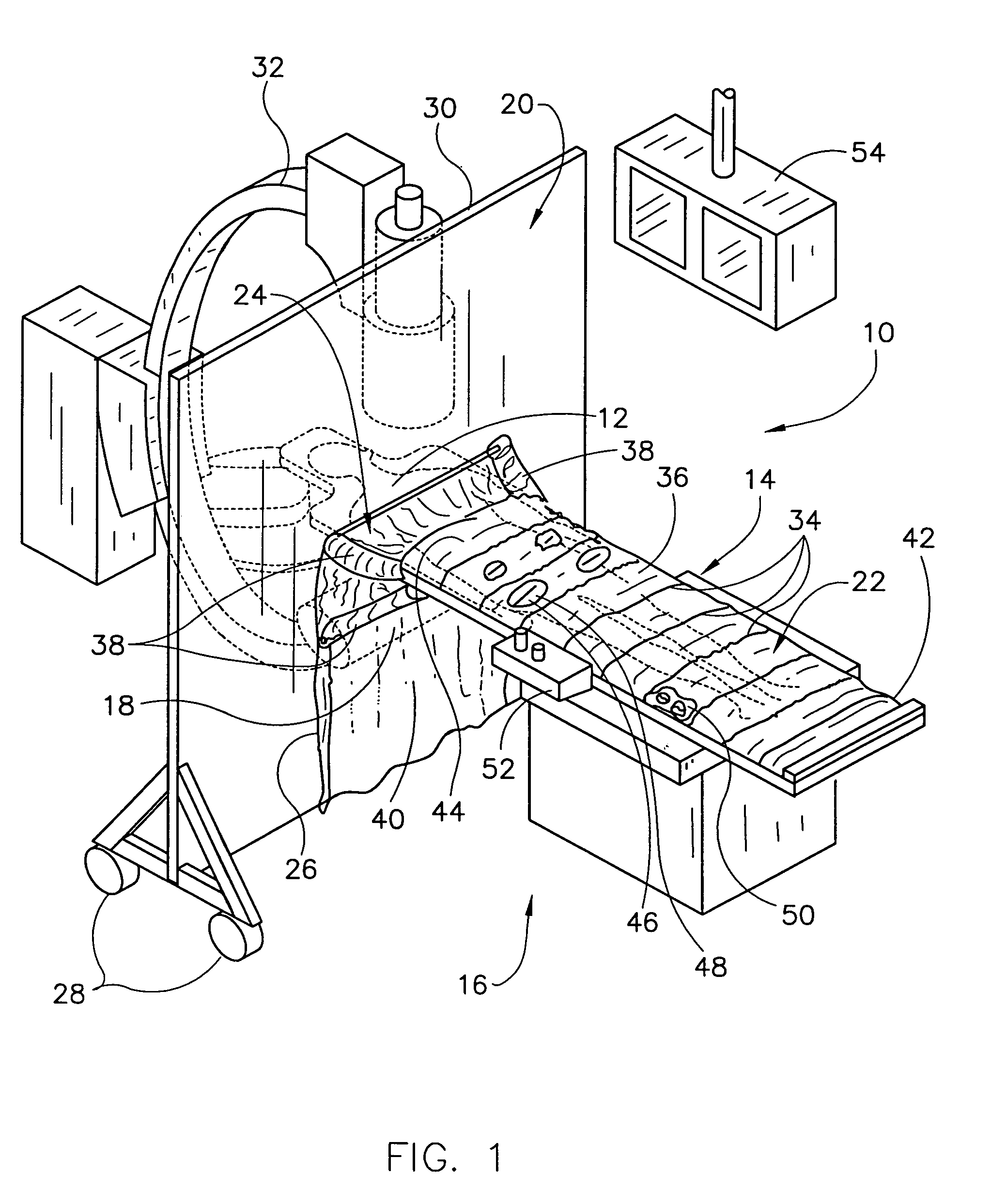
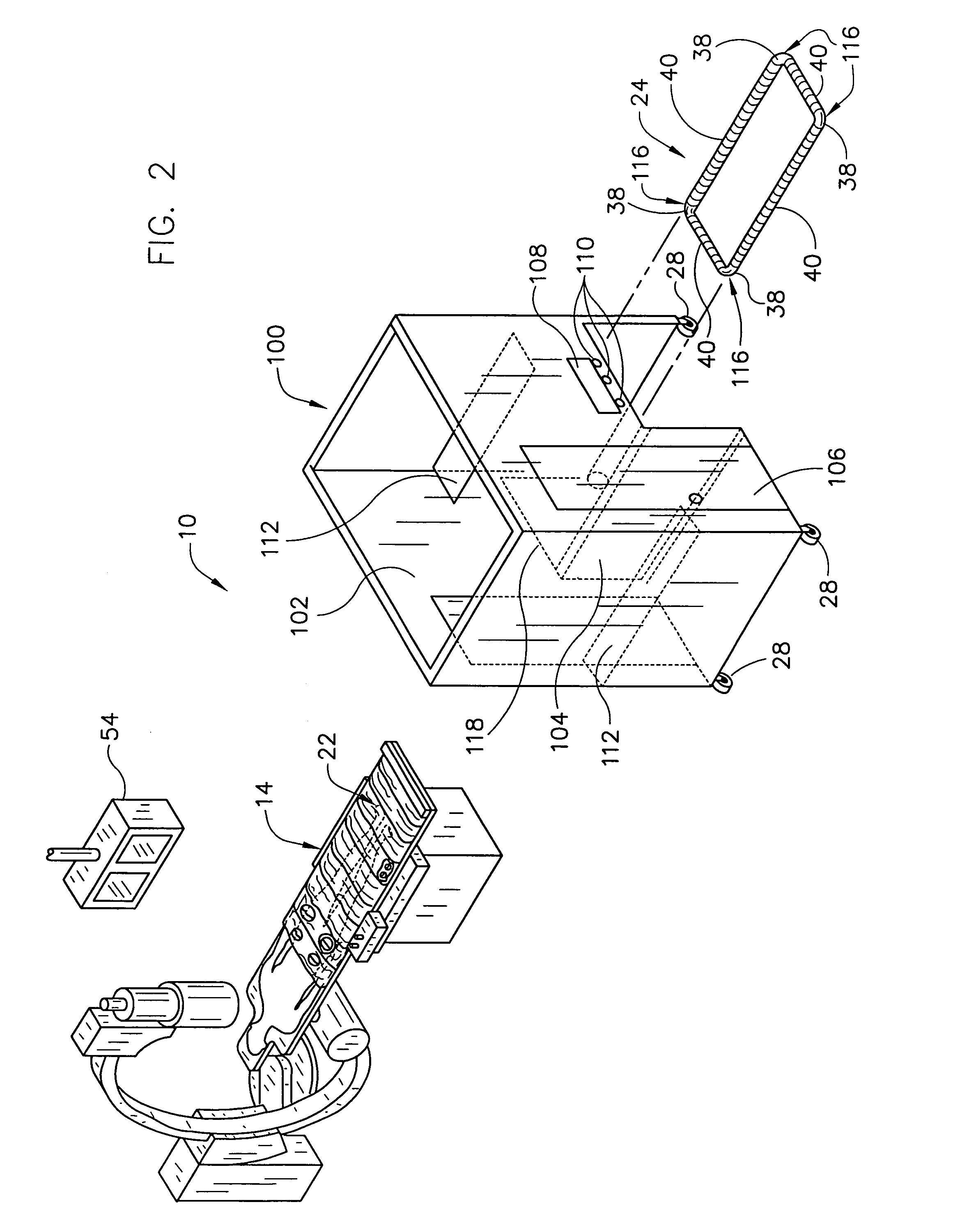
[0032]FIG. 4 illustrates that these embodiments use much the same system for shielding operators and other medical personnel 114 from the x-ray emitter 18 and x-ray scattering when working in the personnel region 16 adjacent to the patient 12 on the x-ray table 14. In particular, operators are shielded from most x-ray radiation by isolating the personnel region 16 from the x-ray emitter 18 with the radiation-shielding wall 102 and the radiation-shielding flexible interface 24, covering the patient with a radiation-shielding screen 22 adjacent to the personnel region, and joining the wall 102 and the screen 22 with the flexible interface 24. The wall 102 and the flexible interface 24 isolate the personnel region 16 from the x-ray emitter 18. The flexible interface 24 attaches the x-ray table 14 to the wall 20, 102 through flexible joints 38, 116 and joins the screen 22 to the wall 20, 102 through a flexible radiation-resistant skirt 40. The second embodiment further isolates the oper...

first embodiment

[0049]As various modifications could be made in the constructions and methods herein described and illustrated without departing from the scope of the invention, it is intended that all matter contained in the foregoing description or shown in the accompanying drawings shall be interpreted as illustrative rather than limiting. For example, the wall 20 in the first embodiment can be curved or hinged to partially surround the operating region 16. As another example, the cubicle 100 can be wider to extend over the foot 42 of the x-ray table 14, thereby enlarging the operating region 16 within the cubicle 100. Thus, the breadth and scope of the present invention should not be limited by any of the above-described exemplary embodiments, but should be defined only in accordance with the following claims appended hereto and their equivalents.


PUM


Abstract

A method of performing a medical procedure includes providing a radiation-shielding cubicle having an interior defining a medical personnel region and including a first wall having an opening therein, locating the cubicle with respect to an x-ray table so a portion of the x-ray table extends through the opening into the interior of the cubicle, and separating medical personnel from an x-ray emitter disposed outside of the cubicle using the first wall to shield the medical personnel from radiation emitted by the x-ray emitter.

Description

PRIORITY STATEMENT[0001]This application is a divisional of U.S. application Ser. No. 09 / 990,073 filed Nov. 21, 2001, now U.S. Pat. No. 6,653,648 which is a continuation-in-part of U.S. application Ser. No. 09 / 638,772 filed Aug. 15, 2000, now U.S. Pat. No. 6,448,571, which are incorporated herein by reference to the extent permitted by law.FIELD OF THE INVENTION[0002]This invention relates generally to radiation protection systems and, more particularly, to radiation shielding systems with integrated procedural environments for use in the course of diagnostic or therapeutic procedures as well as methods for the use of such systems.BACKGROUND OF THE INVENTION[0003]X-rays are used in a wide variety of medical procedures, many of which require medical personnel to be in direct contact with the patient, thereby exposing such personnel to radiation.[0004]As presently configured, x-ray laboratories produce x-ray exposure to the patient and to the operator and associated technicians. Since...

Claims


Application Information

Patent Timeline
Patent Type & Authority Patents(United States)
IPC IPC(8): G21F3/00A61B6/10A61B19/00G21F3/02
CPCA61B6/107G21F3/00G21F3/02G21Y2002/201G21Y2004/303G21Y2002/304G21Y2002/501G21Y2004/30G21Y2002/301A61B6/4423
Inventor GOLDSTEIN, JAMES A.
Owner ECO CATH LAB SYST
Why Eureka
Try Eureka