

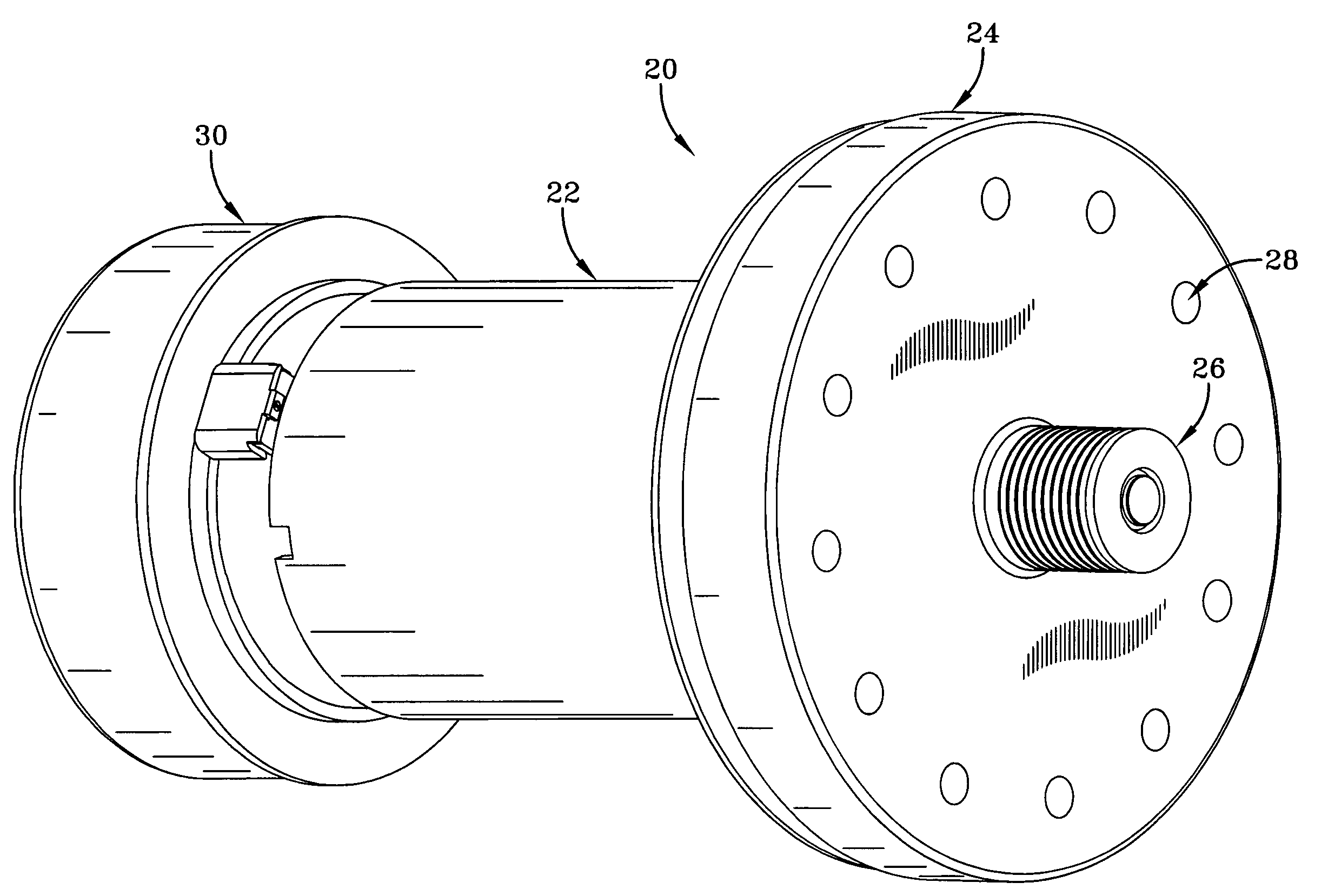
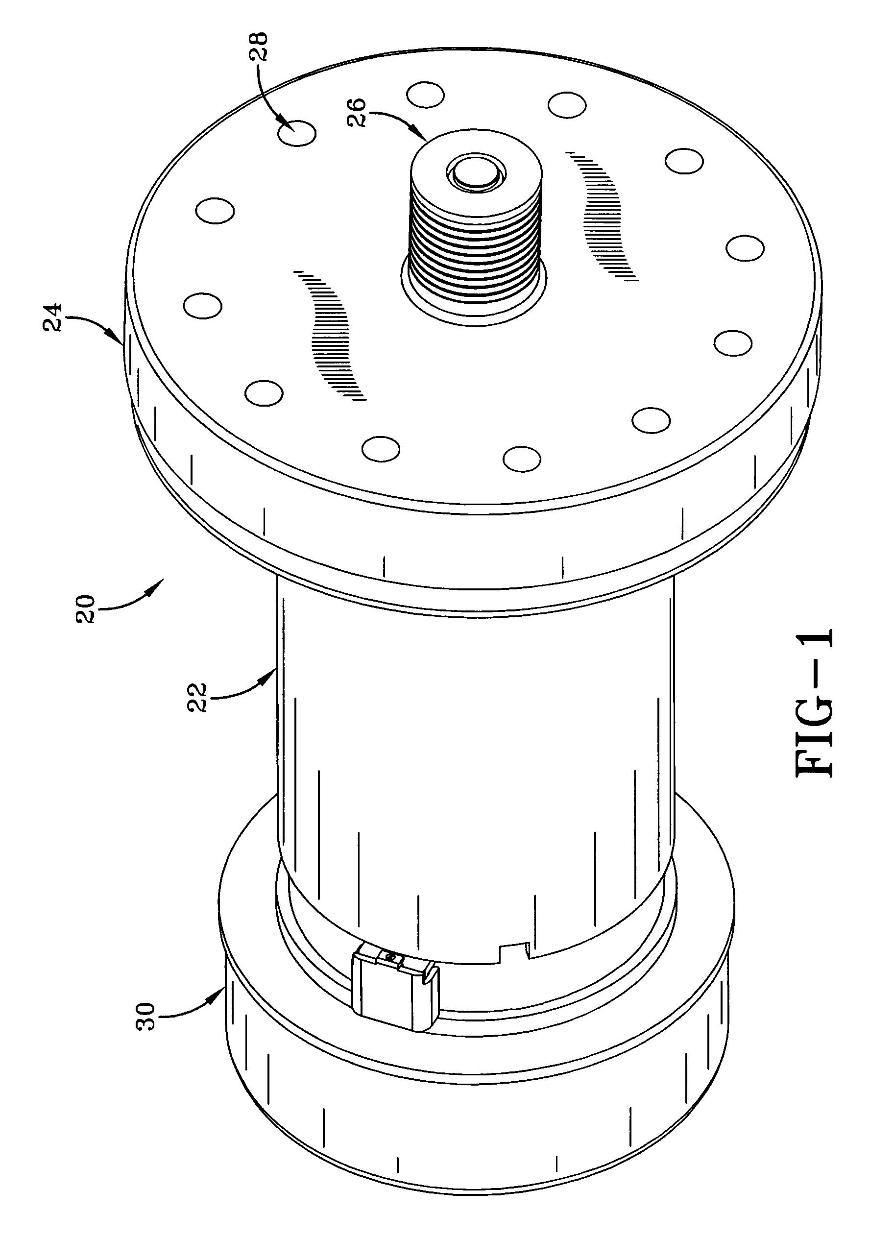
Motor/flywheel assembly with shrouded radial cooling fan
a technology of radial fan and motor, which is applied in the direction of liquid fuel engine, movement coordination device, gymnastic exercise, etc., can solve the problems of excessive noise, excessive noise, and design that is considered to be very inefficien
- Summary
- Abstract
- Description
- Claims
- Application Information
AI Technical Summary
Problems solved by technology
Method used
Image

Examples
first embodiment
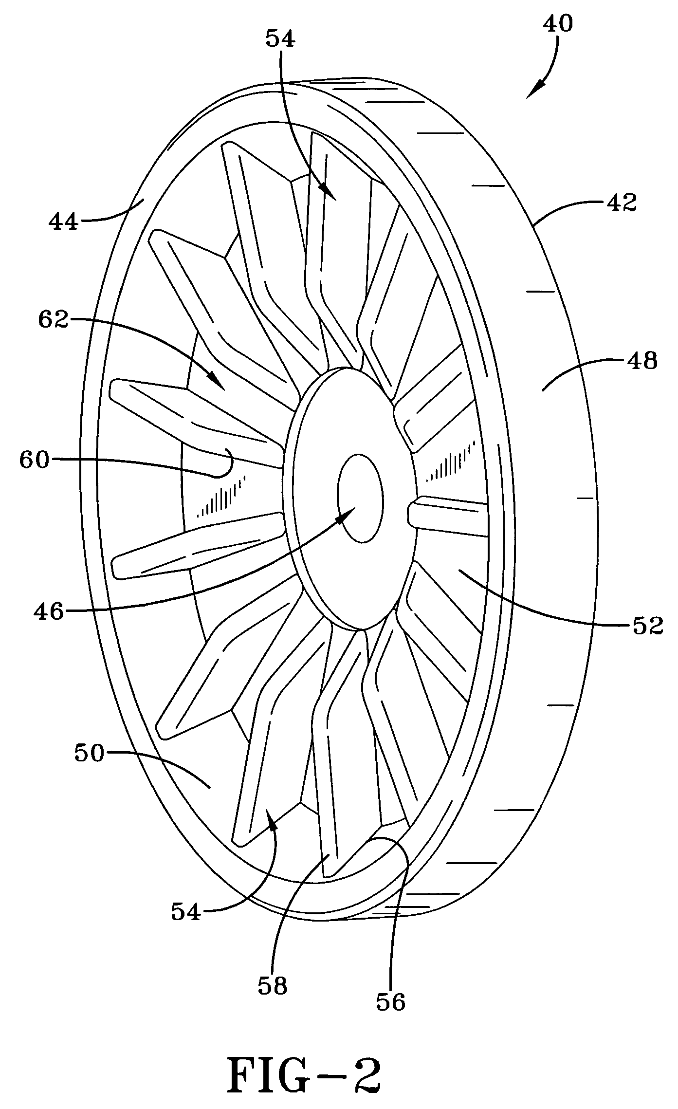
[0031]Referring now to FIGS. 2–4, it can be seen that a flywheel used in the first embodiment is designated generally by the numeral 40. The flywheel 40 includes a pulley side 42 opposite a motor side 44. Extending through the flywheel 40 is a shaft aperture 46. A rim 48 connects the pulley side 42 to the motor side 44, and an inner rim wall 50 extends from the motor side to a plate 52. As is common with most all flywheels, the rim 48 provides a substantial mass to ensure the smooth and continuous operation of the equipment associated with the pulley. It will further be appreciated that the inner rim wall 50 may be angled from the motor side 44 to the plate 52 although it may be perpendicularly configured.
[0032]The flywheel 40 includes a plurality of blades 54 which extend from the plate 52 and are radially configured from the inner rim wall 50 toward the shaft aperture 46. Each blade 54 includes a wall end 56 that is integral with the inner rim wall 50. A wall edge 58 extends along...
second embodiment
[0037]Referring now to FIGS. 5–7, it can be seen that the fan / flywheel assembly 24 includes a flywheel designated generally by the numeral 100. The flywheel 100 is configured similarly to the flywheel 24 but provides some structural differences. In particular, the flywheel 100 includes an axially extending pulley 102 that extends from a pulley side 104. Opposite the pulley side 104 is a motor side 106. The motor side has a plurality of fastener bores 107. Radially disposed and equadistantly spaced about the pulley side 104 are a plurality of balancing bores 108. Extending through the flywheel 100 and the pulley 102 is a shaft aperture 110. Connecting the pulley side 104 to the motor side 106 is a rim 112. An inner rim wall 114 extends from the motor side 106 to a plate 116. The plate 116 is substantially perpendicular to the inner rim wall 114 and extends all the way to the shaft aperture 110.
[0038]The fan assembly, which is designated generally by the numeral 120, is preferably att...
PUM
 Abstract
Description
Claims
Application Information