Optical device for releasable attachment to a microscope

a technology of optical devices and microscopes, which is applied in the field of optical devices for releasable attachment to microscopes, can solve the problems of thermal strain and corrosion, potential damage to the electromechanical components of the electric motor, and damage to the drive motor

Active Publication Date: 2006-08-15
OCULUS OPTIKGERATE GMBH
View PDF10 Cites 12 Cited by
  • Summary
  • Abstract
  • Description
  • Claims
  • Application Information

AI Technical Summary

Benefits of technology

[0006]According to the present invention, the drive motor for remotely controlled adjustment of the lens in the region between the eye and objective of the microscope is integrated in the device, so that the device is released entirely together with the drive motor from the microscope and by suitable methods, can be sterilized. By the integration of the drive motor in the device, the drive shaft for transmission of the drive moment from the drive motor to the device can be eliminated. In addition, the drive movement required for adjustment of the lens within the device is produced by conversion of electrical energy into mechanical energy.
[0007]In order to achieve a sufficient sterilization of the device of the present invention, known methods, for example, autoclave under pressure and temperature effects or steam can be used. These sterilization methods represent a potential risk of damage for the electromechanical components of the electric motor. In particular, damage to the drive motor can result from thermal strain and corrosion. In order to reliably eliminate this type of damage by sterilization methods over long periods of use, the drive motor is encapsulated in a gas- and moisture-sealed housing according to a preferred embodiment of the invention. As a result, the drive motor is insular against the atmosphere of the surrounding environment, so that in the frame of the typical sterilization methods, no gas or moisture can access the electro-mechanical components of the drive motor.
[0008]Each opening in the housing for encapsulated accommodation of the drive motor represents a potential source of malfunction, which requires the use of correspondingly suited sealing features, so that also with longer periods of use, gases or moisture can not enter the interior of the housing. Housing openings that are particularly difficult to seal are those through which a drive movement, for example, with the use of a drive shaft provided on the drive motor, is transferred from the interior of the housing outwardly. According to a preferred embodiment, this problem can be solved by use of a contract-free coupling, in particular, a magnetic coupling. This type of contact-free coupling has a drive part and an output part, whereby the drive movement between the drive part and output part is transferred contact-free, for example, by magnetic fields. In order to avoid a housing opening transferring the drive movement of the drive motor from the interior of the housing outwardly, the drive part of the contact-free acting coupling is encapsulated together with the drive motor. The drive part of the contract-free acting coupling, in contrast, is arranged outside of the housing and thereby makes available the drive moment transferred from the drive motor to the drive part of the coupling outside of the housing.
[0009]In order to provide the drive motor with electrical energy, an electrical cable can be provided, which passes through an opening in the housing and is connected to the drive motor to be electrically conductive. Since the electrical cable itself transfers no movement, the through opening for entry of the electrical cable can be sealed relatively simply from gases and moisture by suitable sealing means. In addition, electrical cables can be fixed in a simple manner along any principle paths on which the cable is laid. Also, the pivoting of the device relative to the microscope is not prevented by the high flexibility of the electrical cable. For sealing of the sealing gap between the housing and the electrical cable, a sealing ring can be provided, which, for example, is fixed by a suitable press nut.

Problems solved by technology

These sterilization methods represent a potential risk of damage for the electromechanical components of the electric motor.
In particular, damage to the drive motor can result from thermal strain and corrosion.
As a result, the drive motor is insular against the atmosphere of the surrounding environment, so that in the frame of the typical sterilization methods, no gas or moisture can access the electro-mechanical components of the drive motor.
Also, the pivoting of the device relative to the microscope is not prevented by the high flexibility of the electrical cable.

Method used


Image

  • Optical device for releasable attachment to a microscope
  • Optical device for releasable attachment to a microscope
  • Optical device for releasable attachment to a microscope

Examples


Embodiment Construction

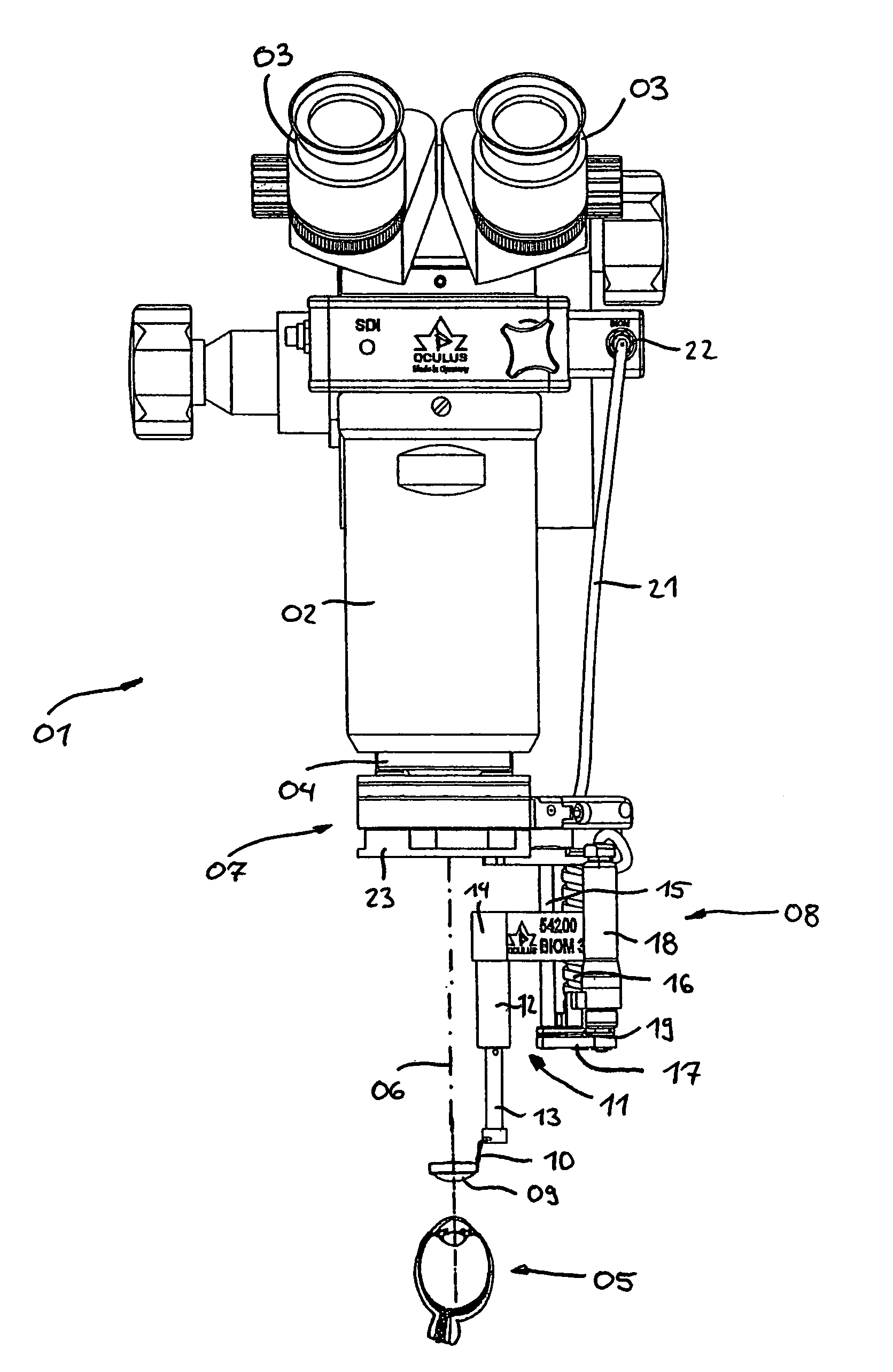
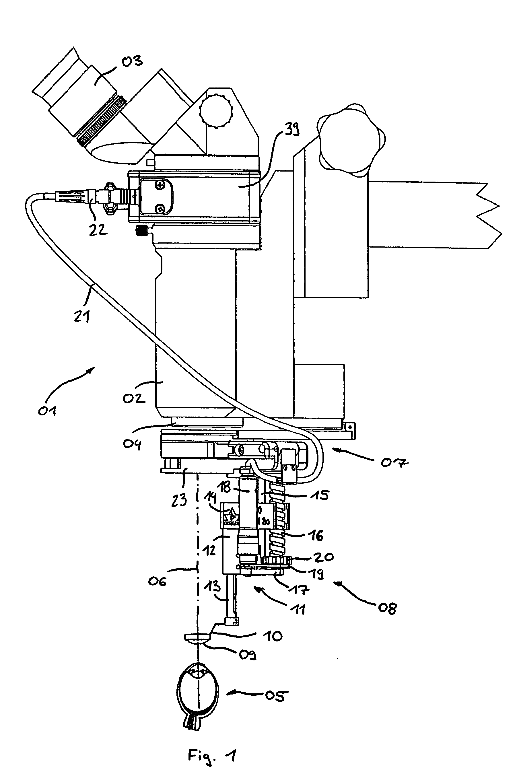
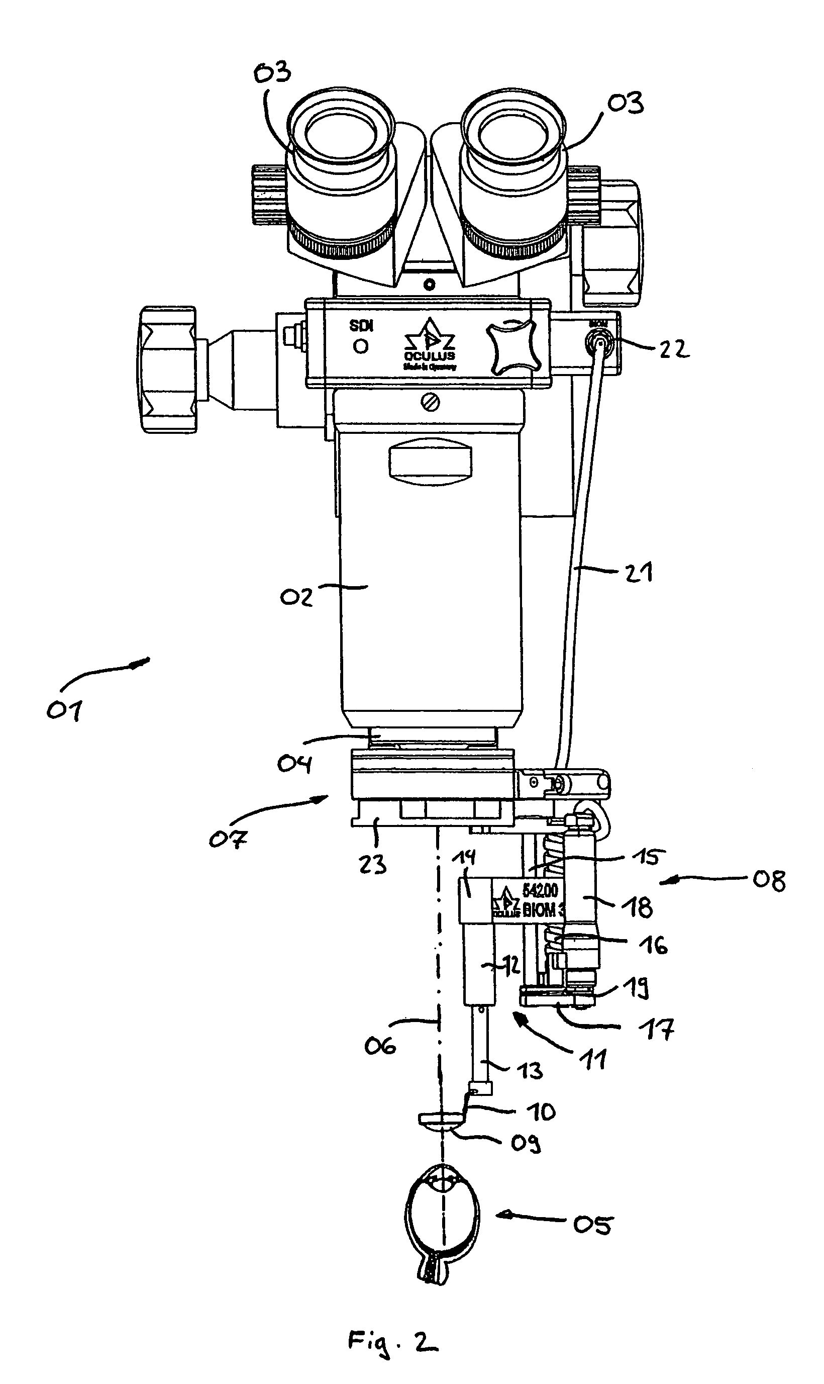
[0024]In FIG. 1, a microscope 01 with a housing 02, an ocular 03, and an objective 04 is shown. The microscope 01 can be used for wide-angle observation of an eye 05 (represented only schematically) during an eye operation. The optical axis 06 can be oriented to the operating area in the eye 05, in order to enable the enlarged observation of the operating area in the ocular 03.

[0025]On the lower side of the housing 02 of the microscope, a holder 07 is attached to the microscope. By means of the holder 07, an optical device according to the present invention can be releasably attached to the microscope 01. The device 08 serves to enable fixing of a lens 09 in the optical path along the optical axis 06. In order to make possible an accurate side to side observation of the movement of the operating instruments in the eye, an inversion prism 39 is also provided in the optical path of the microscope 01. Alternatively thereto, also another suitable inversion device can be used, which also...


PUM


Abstract

A removable optical device with at least one lens for releasable attachment to a microscope suited for contact-free observation of an eye, which can be arranged between the objective of the microscope and the eye in the optical axis of the microscope. A drive device is provided, with which the lens can be adjusted along the optical axis of the microscope, whereby an electric drive motor is integrated in the removable device, which, together with the device, can be detached from the microscope and sterilized by suitable methods.

Description

FIELD OF THE INVENTION[0001]The invention relates to an optical device for releasable attachment to a microscope suited for contact-free observation of the eye.BACKGROUND OF THE INVENTION[0002]In ophthalmology, and particularly with vitreous body surgery, specific devices in combination with correspondingly suited microscopes are used, in order to makes possible a contact-free, wide-angle observation of the eye. In particular, with operations on the eye, optical devices are used, with which the surgeon can observe the movements performed with the operating implements, whereby, by the adjustment of the lens in the region between the objective of the microscope and the eye, focusing in different planes is made possible.[0003]Such a device is known, for example, from EP 11 99 591 A1. With this device, the driving movement of a drive motor provided on the microscope can be transferred with the assistance of a flexible drive shaft on a linear gear provided on the device.[0004]Since the d...

Claims


Application Information

Patent Timeline
Patent Type & Authority Patents(United States)
IPC IPC(8): G02B21/00G02B7/04A61F9/007
CPCG02B21/0012A61B3/13
Inventor KIRCHHUEBEL, RAINER
Owner OCULUS OPTIKGERATE GMBH
Why Eureka
Try Eureka