Current-perpendicular-to-the-plane structure magnetoresistive element and method of making same

Inactive Publication Date: 2006-08-15
FUJITSU LTD
View PDF11 Cites 4 Cited by
  • Summary
  • Abstract
  • Description
  • Claims
  • Application Information

AI Technical Summary

Benefits of technology

[0006]It is accordingly an object of the present invention to provide a current-perpendicular-to-the-plane (CPP) structu

Problems solved by technology

The Barkhausen noise ca

Method used


Image

  • Current-perpendicular-to-the-plane structure magnetoresistive element and method of making same
  • Current-perpendicular-to-the-plane structure magnetoresistive element and method of making same
  • Current-perpendicular-to-the-plane structure magnetoresistive element and method of making same

Examples


Example

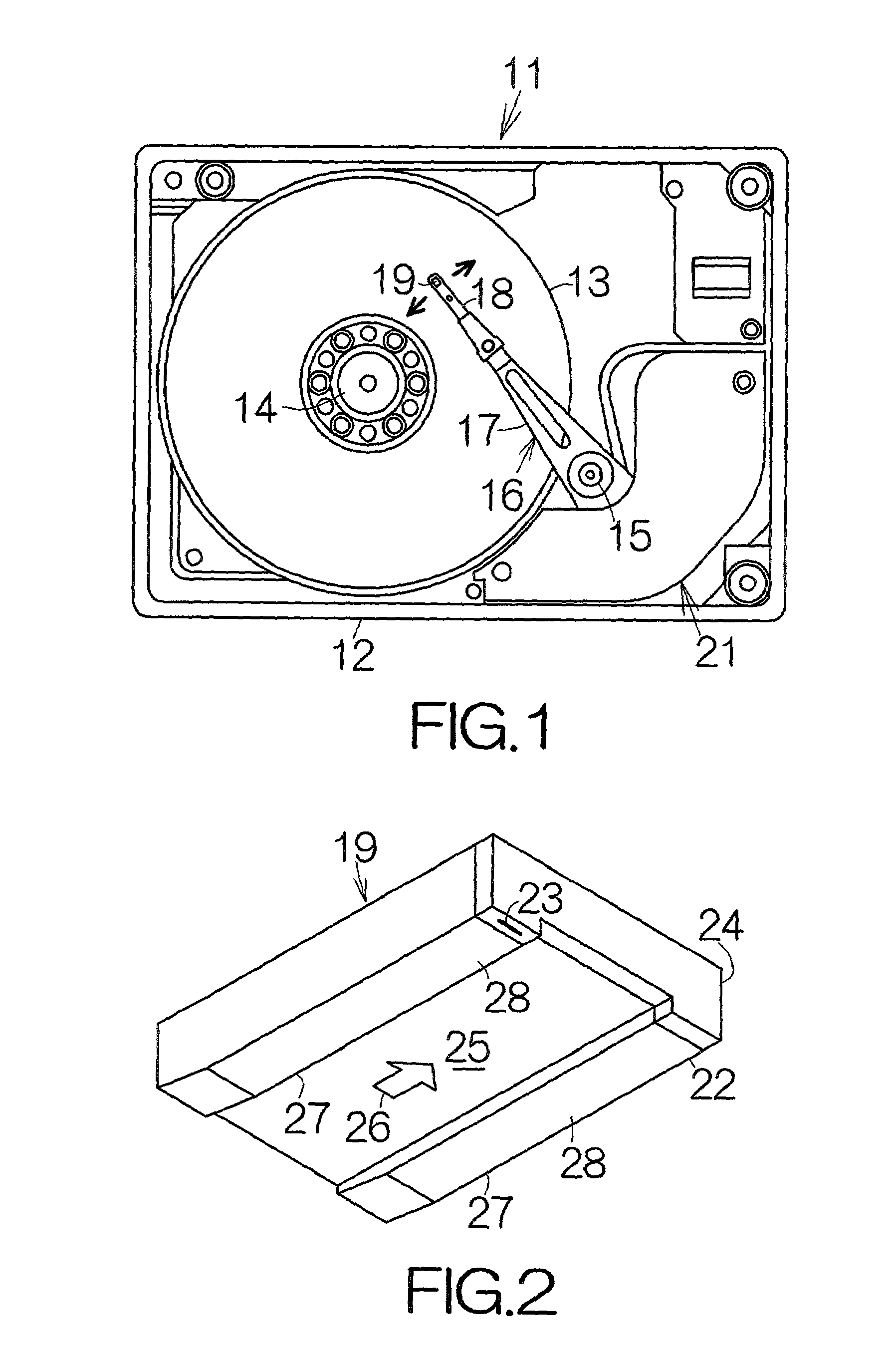
[0026]FIG. 1 schematically illustrates the interior structure of a hard disk drive (HDD) 11 as an example of a magnetic recording medium drive or storage device. The HDD 11 includes a box-shaped primary enclosure 12 defining an inner space of a flat parallelepiped, for example. At least one magnetic recording disk 13 is accommodated in the inner space within the primary enclosure 12. The magnetic recording disk 13 is mounted on a driving shaft of a spindle motor 14. The spindle motor 14 is allowed to drive the magnetic recording disk 13 for rotation at a higher revolution rate such as 7,200 rpm or 10,000 rpm, for example. A cover, not shown, is coupled to the primary enclosure 12 so as to define the closed inner space between the primary enclosure 12 and itself.

[0027]A carriage 16 is also accommodated in the inner space of the primary enclosure 12 for swinging movement about a vertical support shaft 15. The carriage 16 includes a rigid swinging arm 17 extending in the horizontal dir...


PUM

PropertyMeasurementUnit
Thicknessaaaaaaaaaa
Magnetismaaaaaaaaaa
Magnetoresistanceaaaaaaaaaa

Abstract

The upper portion of a magnetoresistive film is interposed between insulators in the lateral direction of a recording track in a current-perpendicular-to-the-plane structure magnetoresistive element. Domain control magnetic layers sandwich the upper portion of the magnetoresistive film along with the insulators in the lateral direction. The insulators serve to establish a narrower path for electric current between the lower portion of the magnetoresistive film and an upper electrode layer. The substantial width in the lateral direction can thus be reduced in the magnetoresistive film. In addition, a longitudinal biasing magnetic field established between the domain control magnetic layers efficiently acts on the magnetoresistive film. In particular, if a free magnetic layer is included in the upper portion of the magnetoresistive film, the free magnetic layer can be subjected to a larger longitudinal biasing magnetic field. A single domain property can be realized in the free ferromagnetic layer enough. The Barkhausen noise can be reduced.

Description

BACKGROUND OF THE INVENTION[0001]1. Field of the Invention[0002]The present invention relates to a magnetoresistive element often utilized in a magnetic recording medium drive such as a magnetic disk drive as well as a magnetic tape drive. In particular, the invention relates to a current-perpendicular-to-the-plane (CPP) structure magnetoresistive element comprising: the lower portion of a magnetoresistive film extending over the surface of a lower magnetic pole layer by a first lateral width; the upper portion of the magnetoresistive film extending over the surface of the lower portion by a second lateral width smaller than the first lateral width; and an upper magnetic pole layer contacting the upper portion of the magnetoresistive film, and a method of making the same.[0003]2. Description of the Prior Art[0004]A magnetoresistive film, such as a spin valve film, usually includes a pinning antiferromagnetic layer, a pinned ferromagnetic layer and a non-magnetic intermediate layer f...

Claims


Application Information

Patent Timeline
IPC IPC(8): G11B5/33G01R33/09G11B5/012G11B5/39H01F10/16H01F10/32H01L43/08H01L43/12
CPCB82Y10/00B82Y25/00G11B5/3903H01F10/3254H01L43/12H01L43/08G11B5/012Y10T29/49046Y10T29/49044Y10T29/49043Y10T29/49041Y10T29/49052H10N50/01H10N50/10
Inventor EGUCHI, SHINKAMATA, CHIKAYOSHIIKEDA, JUNYATANAKA, ATSUSHI
Owner FUJITSU LTD
Why Eureka
Try Eureka