Method of manufacturing magnetoresistive device capable of preventing a sense current from flowing into dead regions of a magnetoresistive element, and method of manufacturing thin-film magnetic head

Inactive Publication Date: 2006-08-01
TDK CORPARATION
View PDF15 Cites 0 Cited by
  • Summary
  • Abstract
  • Description
  • Claims
  • Application Information

AI Technical Summary

Benefits of technology

[0024]It is an object of the invention to provide a magnetoresistive device and a methods of manufacturing the same, a thin-film magnetic head and a

Problems solved by technology

If Barkhausen noise occurs, an abrupt variation in output results, which induces a reduction in signal-to-noise (S/N) ratio and an increase in error rate.
However, a problem is that it is inevitable that a sense current flows into dead regions created in the free layer even though the overlapping elec

Method used


Image

  • Method of manufacturing magnetoresistive device capable of preventing a sense current from flowing into dead regions of a magnetoresistive element, and method of manufacturing thin-film magnetic head
  • Method of manufacturing magnetoresistive device capable of preventing a sense current from flowing into dead regions of a magnetoresistive element, and method of manufacturing thin-film magnetic head
  • Method of manufacturing magnetoresistive device capable of preventing a sense current from flowing into dead regions of a magnetoresistive element, and method of manufacturing thin-film magnetic head

Examples


first embodiment

[0069]Reference is now made to FIG. 6A to FIG. 9A and FIG. 6B to FIG. 9B to describe a thin-film magnetic head and an outline of a method of manufacturing the same of a first embodiment of the invention. FIG. 6A to FIG. 9A are cross sections each orthogonal to the air bearing surface. FIG. 6B to FIG. 9B are cross sections of the pole portion each parallel to the air bearing surface.

[0070]In the manufacturing method, as shown in FIG. 6A and FIG. 6B, an insulating layer 2 made of an insulating material such as alumina (Al2O3) or silicon dioxide (SiO2) whose thickness is 1 to 20 μm, for example, is formed through sputtering, for example, on a substrate 1 made of a ceramic material such as aluminum oxide and titanium carbide (Al2O3—TiC). On the insulating layer 2 a bottom shield layer 3 having a thickness of 0.1 to 5 μm, for example, is formed for making a read head. The bottom shield layer 3 is made of a magnetic material such as FeAlSi, NiFe, CoFe, CoFeNi, FeN, FeZrN, FeTaN, CoZrNb, o...

second embodiment

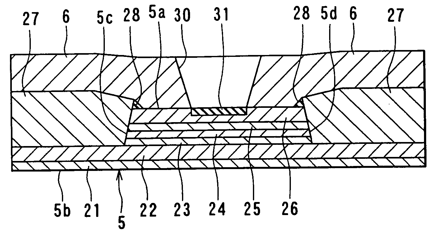
[0134]Reference is now made to FIG. 16 to describe a magnetoresistive device and a method of manufacturing the same, a thin-film magnetic head and a method of manufacturing the same, a head gimbal assembly and a hard disk drive of a second embodiment of the invention. FIG. 16 is a cross section of the magnetoresistive device of the embodiment that is parallel to the air bearing surface.

[0135]According to the magnetoresistive device of the embodiment, the high resistance layer 31 of the MR element 5 is formed through increasing the resistance of the part of the protection layer 26 located in the region between the two electrode layers 6 entirely.

[0136]The method of manufacturing the magnetoresistive device of the second embodiment includes the steps performed until the electrode layers 6 are formed that are similar to those of the first embodiment, as shown in FIG. 1. Through these steps part of the top surface of the protection layer 26 is natural-oxidized and made to have a high re...

third embodiment

[0140]Reference is now made to FIG. 17 to describe a magnetoresistive device and a method of manufacturing the same, a thin-film magnetic head and a method of manufacturing the same, a head gimbal assembly and a hard disk drive of a third embodiment of the invention. FIG. 17 is a cross section of the magnetoresistive device of the embodiment that is parallel to the air bearing surface.

[0141]According to the magnetoresistive device of the third embodiment, the protection layer of the MR element 5 is an Al layer 26a. The high resistance layer 31 of the MR element 5 is an Al2O3 layer. The high resistance layer 31 is formed through increasing the resistance of the part of the Al layer 26a that is the protection layer located in the region between the two electrode layers 6 entirely.

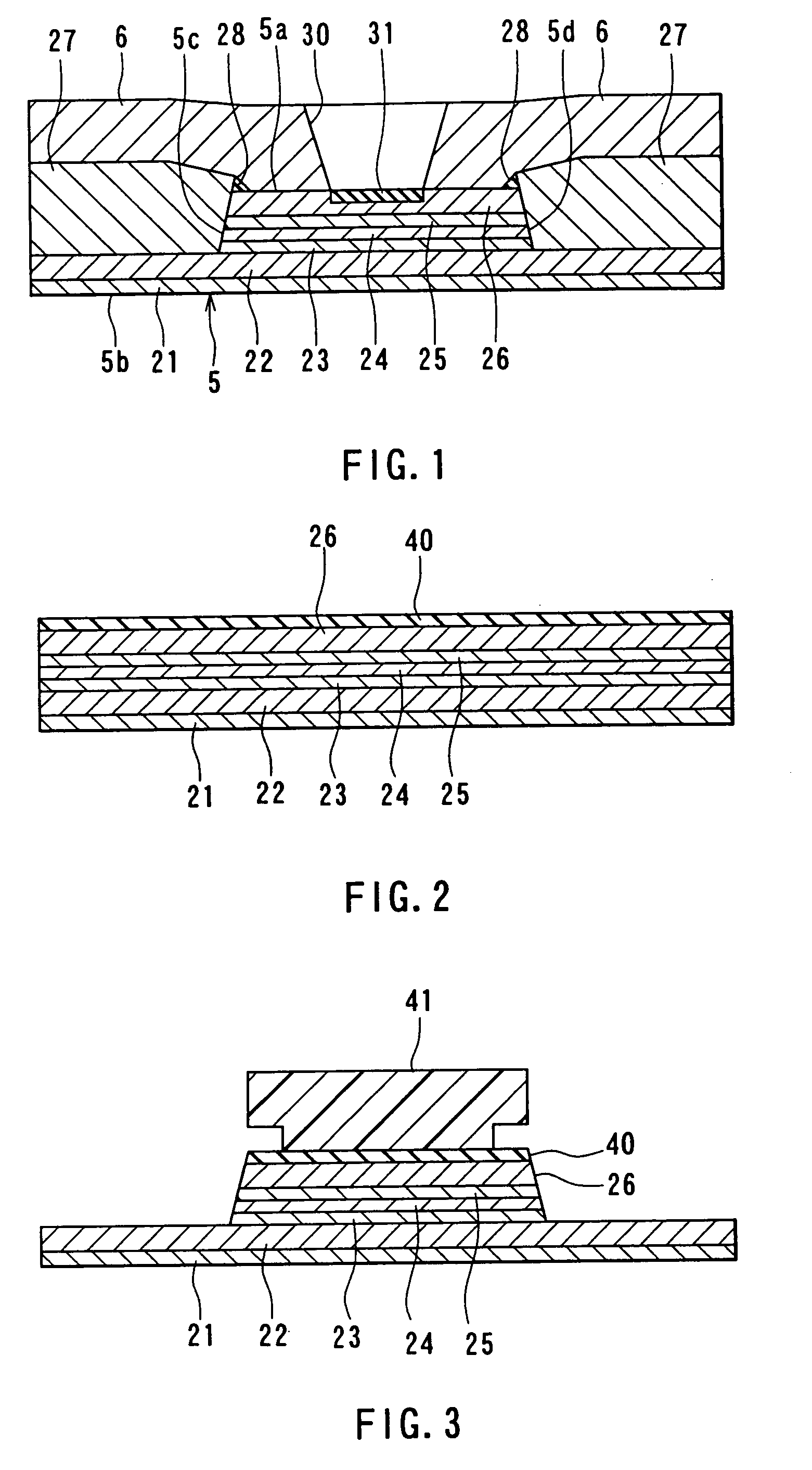
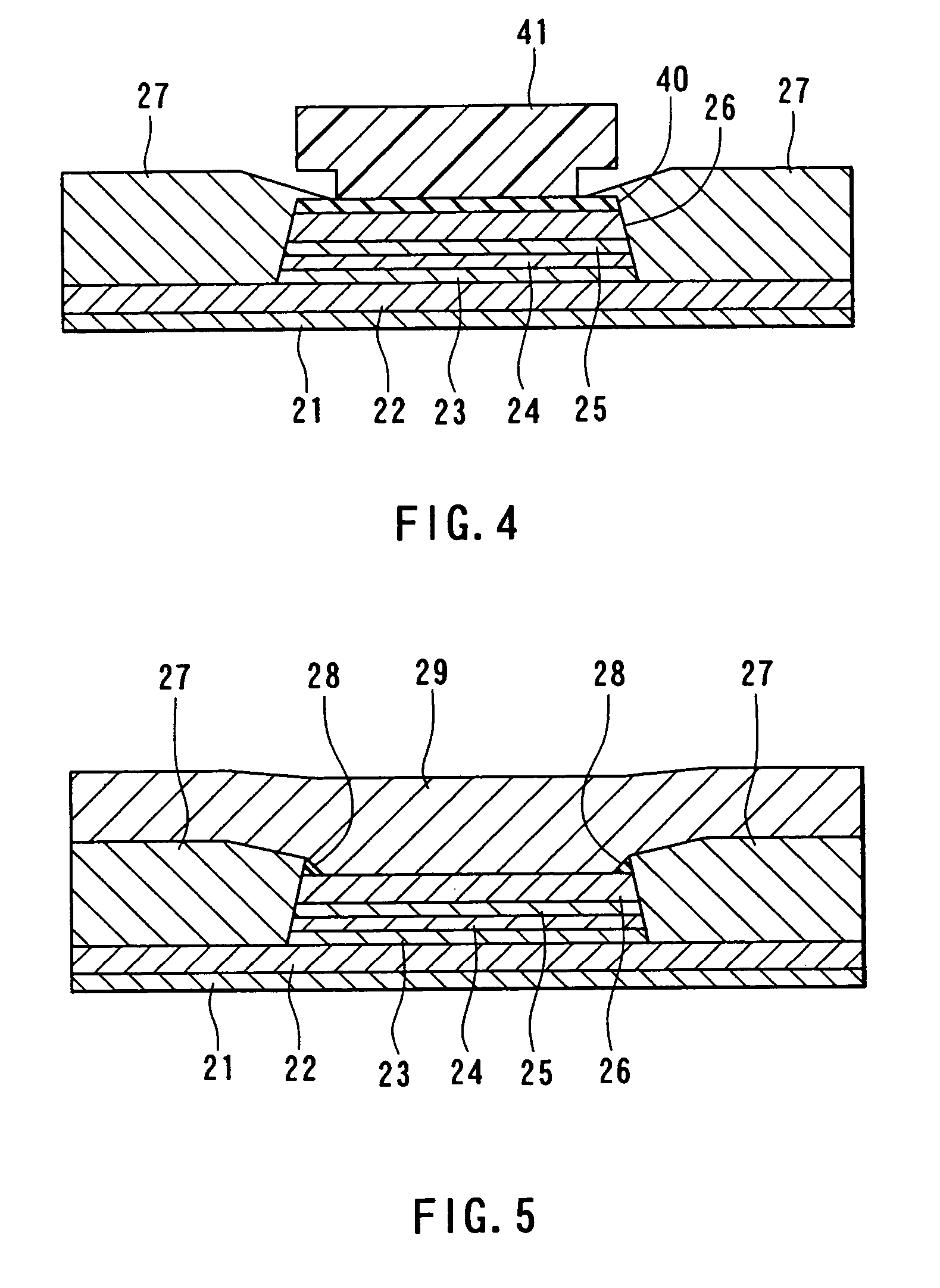
[0142]Reference is now made to FIG. 17 to FIG. 22 to describe a method of manufacturing the magnetoresistive device of the third embodiment. In the method, as shown in FIG. 18, the base layer 21, the antiferr...


PUM

PropertyMeasurementUnit
Antiferromagnetismaaaaaaaaaa
Electrical resistanceaaaaaaaaaa
Magnetizationaaaaaaaaaa

Abstract

A magnetoresisive device comprises: an MR element having two surfaces that face toward opposite directions and two side portions that face toward opposite directions; two bias field applying layers that are located adjacent to the side portions of the MR element and apply a longitudinal bias magnetic field to the MR element; and two electrode layers that are located adjacent to one of the surfaces of each of the bias field applying layers and feed a sense current to the MR element. The electrode layers overlap the one of the surfaces of the MR element. The magnetoresistive device further comprises two nonconductive layers that are located between the one of the surfaces of the MR element and the two electrode layers and located in two regions that include ends of the MR element near the side portions thereof, the two regions being parts of the region in which the electrode layers face toward the one of the surfaces of the MR element.

Description

[0001]This is a Division of application Ser. No. 09 / 920,821 filed Aug. 3, 2001, now U.S. Pat. No. 6,657,826. The entire disclosure of the prior application is hereby incorporated by reference herein in its entirety.BACKGROUND OF THE INVENTION[0002]1. Field of the Invention[0003]The present invention relates to a magnetoresistive device that incorporates a magnetoresistive element and a method of manufacturing such a magnetoresistive device, a thin-film magnetic head that incorporates a magnetoresistive device that functions as a device for reading a magnetic signal and a method of manufacturing such a thin-film magnetic head, a head gimbal assembly, and a hard disk drive.[0004]2. Description of the Related Art[0005]Performance improvements in thin-film magnetic heads have been sought as areal recording density of hard disk drives has increased. Such thin-film magnetic heads include composite thin-film magnetic heads that have been widely used. A composite head is made of a layered s...

Claims


Application Information

Patent Timeline
IPC IPC(8): G11B5/127H04R31/00G01R33/09G11B5/012G11B5/39G11B5/48H01F10/16H01F10/28H01F10/30H01F41/18H01L43/08H01L43/12
CPCB82Y10/00B82Y25/00G11B5/3903G11B5/012G11B5/4806Y10T29/49032Y10T29/49046Y10T29/49048Y10T29/49043Y10T29/49044Y10T29/49052G11B2005/3996
Inventor SHIMAZAWA, KOJITERUNUMA, KOICHI
Owner TDK CORPARATION
Why Eureka
Try Eureka