Parallel keystream decoder

Active Publication Date: 2006-08-15
XILINX INC
View PDF6 Cites 12 Cited by
  • Summary
  • Abstract
  • Description
  • Claims
  • Application Information

AI Technical Summary

Problems solved by technology

For large keystreams this may be a performance issue.
However, an FPGA may be unsuitable to host a serial LFSR that is to operate at very high frequencies.
Even though an FPGA may be unable to implement an LFSR operating at some highest clock-rate, the s

Method used


Image

  • Parallel keystream decoder
  • Parallel keystream decoder
  • Parallel keystream decoder

Examples


Embodiment Construction

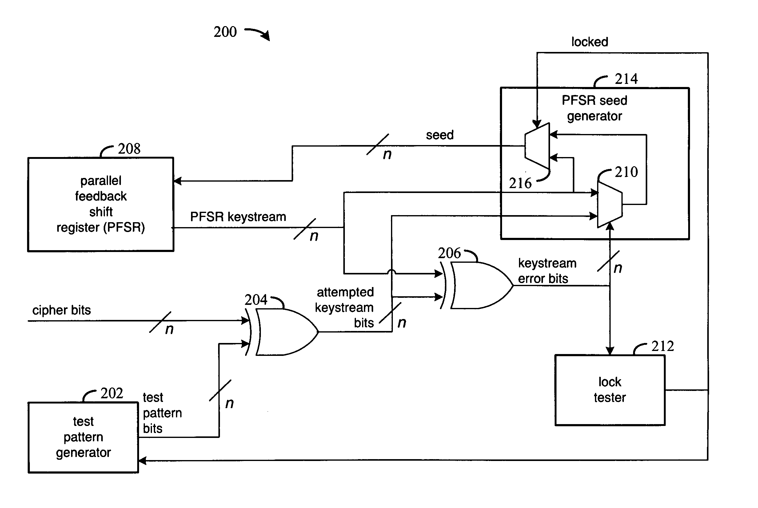
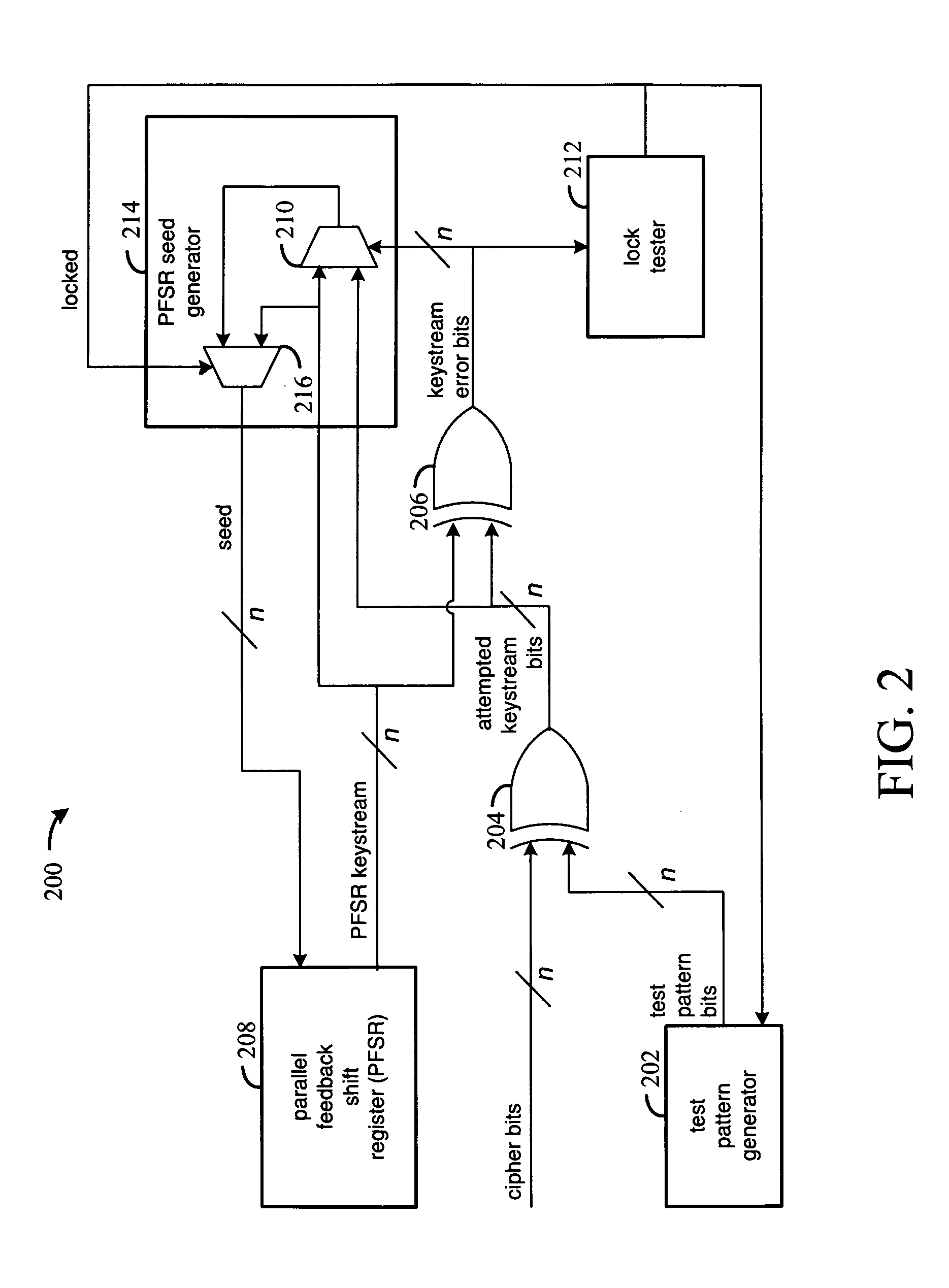
[0019]The various embodiments of the present invention decode a keystream in parallel. Test pattern bits are generated and compared in parallel to input cipher bits, and the result of that comparison, referred to as the attempted keystream, is compared to a current keystream. A parallel-feedback shift register (PFSR) generates the current keystream bits in parallel. The feedback to the PFSR is based on either the value of the current keystream or the attempted keystream, depending on whether the current keystream matches the attempted keystream. Once the two keystreams match, the current keystream is used for feedback. Otherwise the attempted keystream is used for feedback.

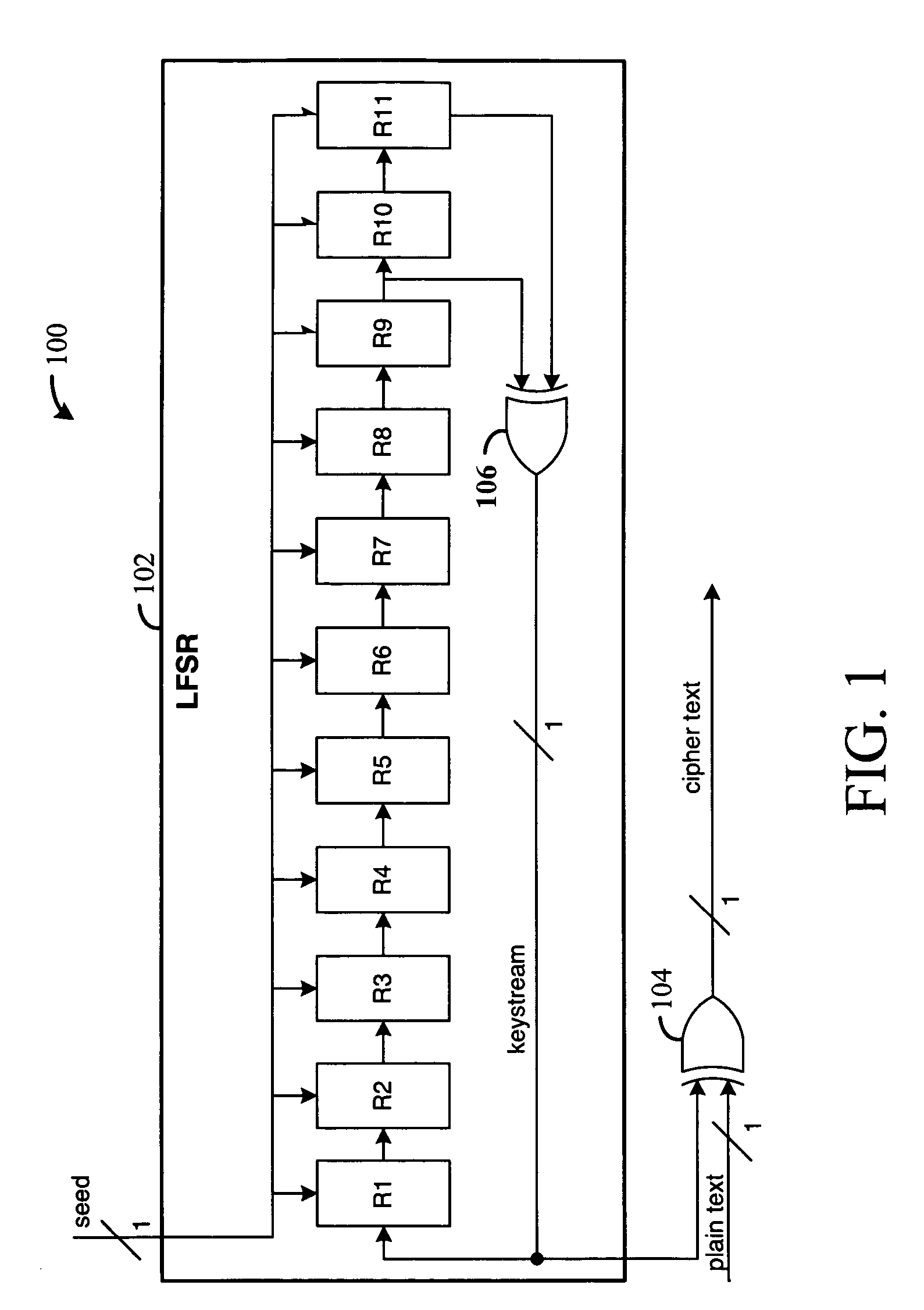
[0020]FIG. 1 illustrates an example serial stream cipher 100. A serial stream cipher generally includes two components, a linear feedback shift register (LFSR) 102 and an encryption unit, which in the example cipher is exclusive-or (XOR) gate 104.

[0021]LFSRs include a sequence of registers, for example, R1–R11, an...


PUM


Abstract

Methods and circuitry are disclosed for decoding a keystream. A set of test bits is generated, and a set of attempted keystream bits are generated from differences between the test bits and an input set of cipher bits. A set of current keystream bits are generated from a current seed using a parallel feedback shift register, and the attempted keystream bits are compared to the current keystream bits. In response to attempted keystream bits being equal to the current keystream bits, the current keystream bits are fed back as a new current seed. In response to attempted keystream bits being not equal to the current keystream bits, the attempted keystream bits are fed back as the new current seed.

Description

FIELD OF THE INVENTION[0001]The present invention generally relates to keystream decoders.BACKGROUND[0002]Encryption-based data transmission schemes generally encode data using a random key. The original data may be referred to as plain text, the encryption key referred to as the keystream, and the resulting encrypted data referred to as the cipher text. The terms bits will sometimes be used in place of text in this description to indicate the binary representation of the text.[0003]A transmitter encodes data using a selected keystream, and a receiver decodes the data using the same keystream. In some applications the receiver may be initially unaware of the keystream used by the transmitter. In these applications, the receiver applies different keystreams to received cipher text until the cipher text is successfully decoded. The keystream may be determined from a training pattern that is sent by the transmitter and known to the receiver. Once the receiver has decoded the cipher tex...

Claims


Application Information

Patent Timeline
IPC IPC(8): G06F17/00
CPCH04L9/065H04L2209/34H04L2209/125
Inventor CAMPBELL, SCOTT J.FISCHABER, THOMAS E.
Owner XILINX INC
Why Eureka
Try Eureka