Register rename array with individual thread bits set upon allocation and cleared upon instruction completion

a register rename array and array technology, applied in the field of methods and circuitry of the processor, can solve the problems of reducing the return rate of instruction, affecting the efficiency of instruction execution,

Inactive Publication Date: 2006-08-15
IBM CORP
View PDF6 Cites 43 Cited by
  • Summary
  • Abstract
  • Description
  • Claims
  • Application Information

AI Technical Summary

Benefits of technology

[0022]A single rename register (RR) array is used in an SMT processor for a specific architected register such as floating point source condition register (FPSCR). Two bits are added to each rename register entry of the rename register array, one complete thread bit for thread zero (CTB0) and one bit for thread one (CTB1). The CTB bits are all set to a logic value on power on or start-up. A control instruction (CI) that sets control bits used by other in

Problems solved by technology

The only problem is that these instructions also have a tendency to depend upon the outcome of prior instructions.
However, using this technique has achieved a rather impressive downturn in the rate of increased performance and in fact has been showing diminishing returns.
Assuming that the application is written to execute in a parallel manner (multithreaded), there are inherent difficulties in making the program written in this fashion execute faster proportional to the number of added processors.
However, there are problems with CMP.
In this way, a CMP chip is comparatively less flexible for general use, because if there is only one thread, an entire half of the allotted resources are idle and completely useless (just as adding another processor in a system that uses a singly threaded program is useless in a traditional multiprocessor (MP) system).
So, it can only store as many threads as there are physical locations for each of these threads to store the state of their execution.
Whereas much of a CMP processor remains idle when running a single thread and the more processors on the CMP chip makes this problem more pronounced, an SMT processor can dedicate all functional units to the single thread.
However, in some instances, this disrupts the traditional organization of data, as well as instruction flow.
The branch prediction unit becomes less effective when shared,

Method used


Image

  • Register rename array with individual thread bits set upon allocation and cleared upon instruction completion
  • Register rename array with individual thread bits set upon allocation and cleared upon instruction completion
  • Register rename array with individual thread bits set upon allocation and cleared upon instruction completion

Examples


Embodiment Construction

[0031]In the following description, numerous specific details are set forth to provide a thorough understanding of the present invention. However, it will be obvious to those skilled in the art that the present invention may be practiced without such specific details. In other instances, well-known circuits may be shown in block diagram form in order not to obscure the present invention in unnecessary detail. For the most part, details concerning timing, data formats within communication protocols, and the like have been omitted inasmuch as such details are not necessary to obtain a complete understanding of the present invention and are within the skills of persons of ordinary skill in the relevant art.

[0032]Refer now to the drawings wherein depicted elements are not necessarily shown to scale and wherein like or similar elements are designated by the same reference numeral through the several views.

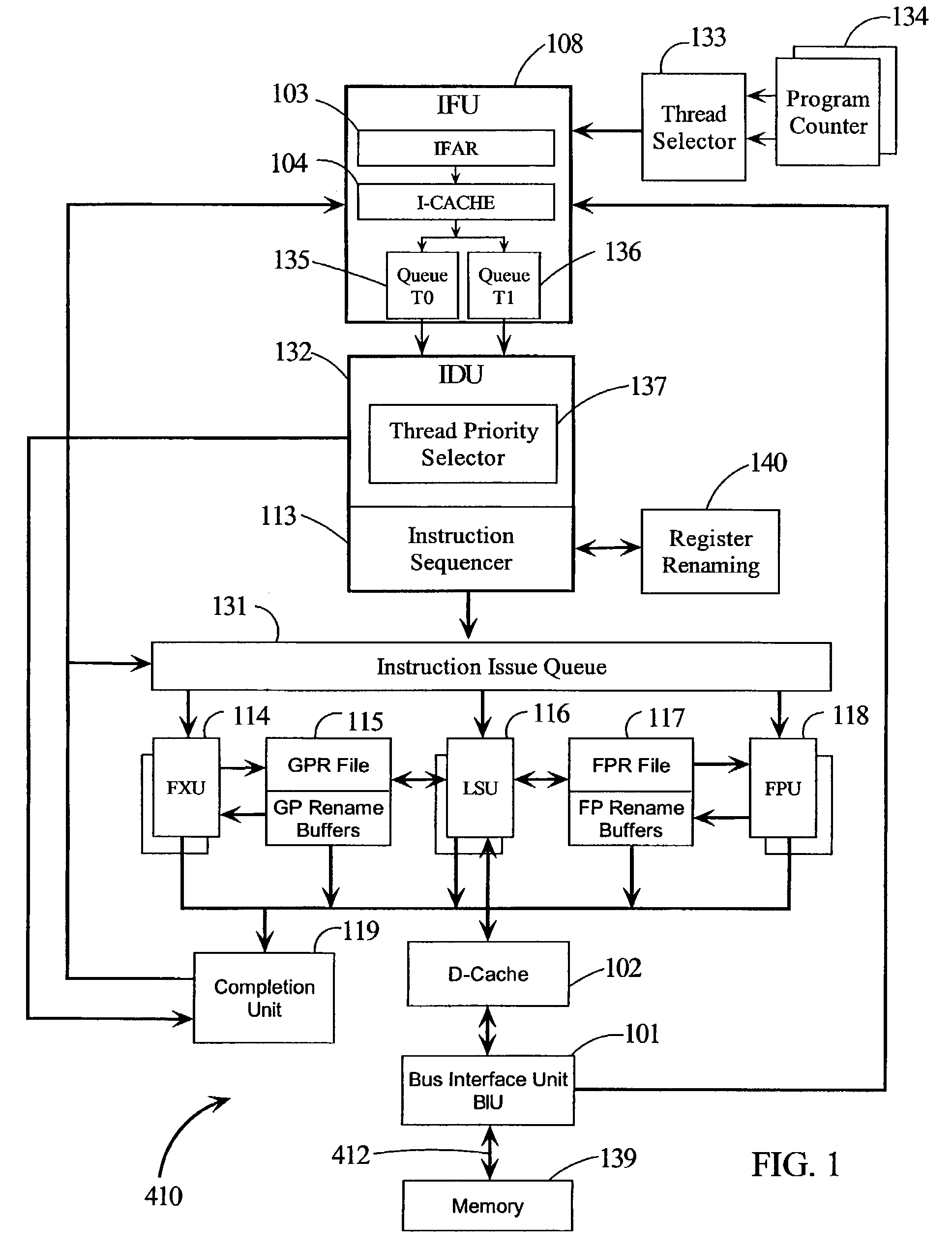
[0033]Referring to FIG. 1, there are illustrated details of CPU 410. CPU 410 is des...


PUM


Abstract

A single rename register array is used in an SMT processor. Two bits are added to each register address of the rename register array, one for bit for thread zero (CTB0) and one bit for thread one (CTB1). The CTB bits are all set to a logic value on power on or start-up. A control instruction (CI) that sets control bits used by other instructions is assigned a register in the rename register array having an address designated as pointer (PTR) address. When a control instruction with an assigned entry with PTR address M completes, then the CTB bit at the PTR address M is flipped to its opposite logic state; likewise, its Valid bit is set to a “not” Valid state. The self resetting CTB bit is used to determine whether an issued instruction sources a register in the rename register array or a corresponding architected register.

Description

TECHNICAL FIELD[0001]The present invention relates in general to methods and circuitry for a processor having simultaneous multithreading (SMT) and single thread operation modes.BACKGROUND INFORMATION[0002]For a long time, the secret to more performance was to execute more instructions per cycle, otherwise known as Instruction Level Parallelism (ILP), or decreasing the latency of instructions. To execute more instructions each cycle, more functional units (e.g., integer, floating point, load / store units, etc.) have to be added. In order to more consistently execute multiple instructions, a processing paradigm called out-of-order processing (OOP) may be used, and in fact, this type of processing has become mainstream.[0003]OOP arose because many instructions are dependent upon the outcome of other instructions, which have already been sent into the processing pipeline. To help alleviate this problem, a larger number of instructions are stored in order to allow immediate execution. Th...

Claims


Application Information

Patent Timeline
IPC IPC(8): G06F9/38G06F9/46G06F9/30
CPCG06F9/3838G06F9/3851G06F9/384
Inventor AMBEKAR, ASIT S.NGUYEN, DUNG Q.YEUNG, RAYMOND C.
Owner IBM CORP
Why Eureka
Try Eureka