Control apparatus and self-diagnostic method for electronic control system

a control apparatus and electronic control system technology, applied in the direction of testing/monitoring control systems, process and machine control, instruments, etc., can solve the problems of harm to the self-diagnostic function, and the inability to perform reliable operation. , to achieve the effect of high reliability

Inactive Publication Date: 2006-08-15
FUJITSU GENERAL LTD
View PDF16 Cites 16 Cited by
  • Summary
  • Abstract
  • Description
  • Claims
  • Application Information

AI Technical Summary

Benefits of technology

[0010]An object of the invention is to provide a control apparatus capable of using data such as a self-diagnostic result with high reliability even in case that a disturbance factor such as an abnormal drop in power source voltage occurs, and a self-diagnostic method in an electronic control system.
[0012]According to the invention, a control apparatus receives data sent from plural electronic devices connected via a communication line by serial communication, and includes condition setting means, disturbance detection means and data processing means. A condition corresponding to a period necessary to receive data by the serial communication from the plural electronic devices is preset in the condition setting means. The disturbance detection means detects a disturbance factor presumed to cause an abnormal operation in at least one of the electronic devices. When the disturbance detection means detects the disturbance factor, the data processing means ignores data from the plural electronic devices for a period by which the condition set in the condition setting means is satisfied. A period for which data is ignored since there is no reliability of data sent by the serial communication from the electronic devices when the disturbance factor occurs is set corresponding to a period necessary to receive data by the serial communication from the plural electronic devices, so that data in which there is a possibility that an abnormal operation occurs is ignored properly and only the data with high reliability can be used. Detection of the disturbance factor is performed by the disturbance detection means of the control apparatus, so that the detection can be used in common with each of the electronic devices and a configuration of an electronic control system structured by the control apparatus and the plural electronic devices can be simplified to achieve cost reduction.
[0016]According to the invention, data communicated in serial is ignored until the time necessary for serial communications with all the electronic devices elapses, so that an operation for ignoring data with low reliability can be performed by a simple determination on whether or not the time has elapsed.
[0017]According to another aspect of the invention, the condition setting means prolongs the time in accordance with an increase of the disturbance factor detected by the disturbance detection means.

Problems solved by technology

At a time of an abnormal drop in power source voltage, a reliable operation cannot be performed.
Since the data from the power device No.2 is received when the low-voltage detection signal indicates abnormal state, there is a possibility that a self-diagnostic function performs wrong detection.
Thus, even when the low-voltage detection signal returns from abnormal state to normality state subsequent to time t1, there is a possibility that abnormal data is received in the control apparatus 11, causing harm to self-diagnosis of the electronic control system 10.

Method used


Image

  • Control apparatus and self-diagnostic method for electronic control system
  • Control apparatus and self-diagnostic method for electronic control system
  • Control apparatus and self-diagnostic method for electronic control system

Examples


first embodiment

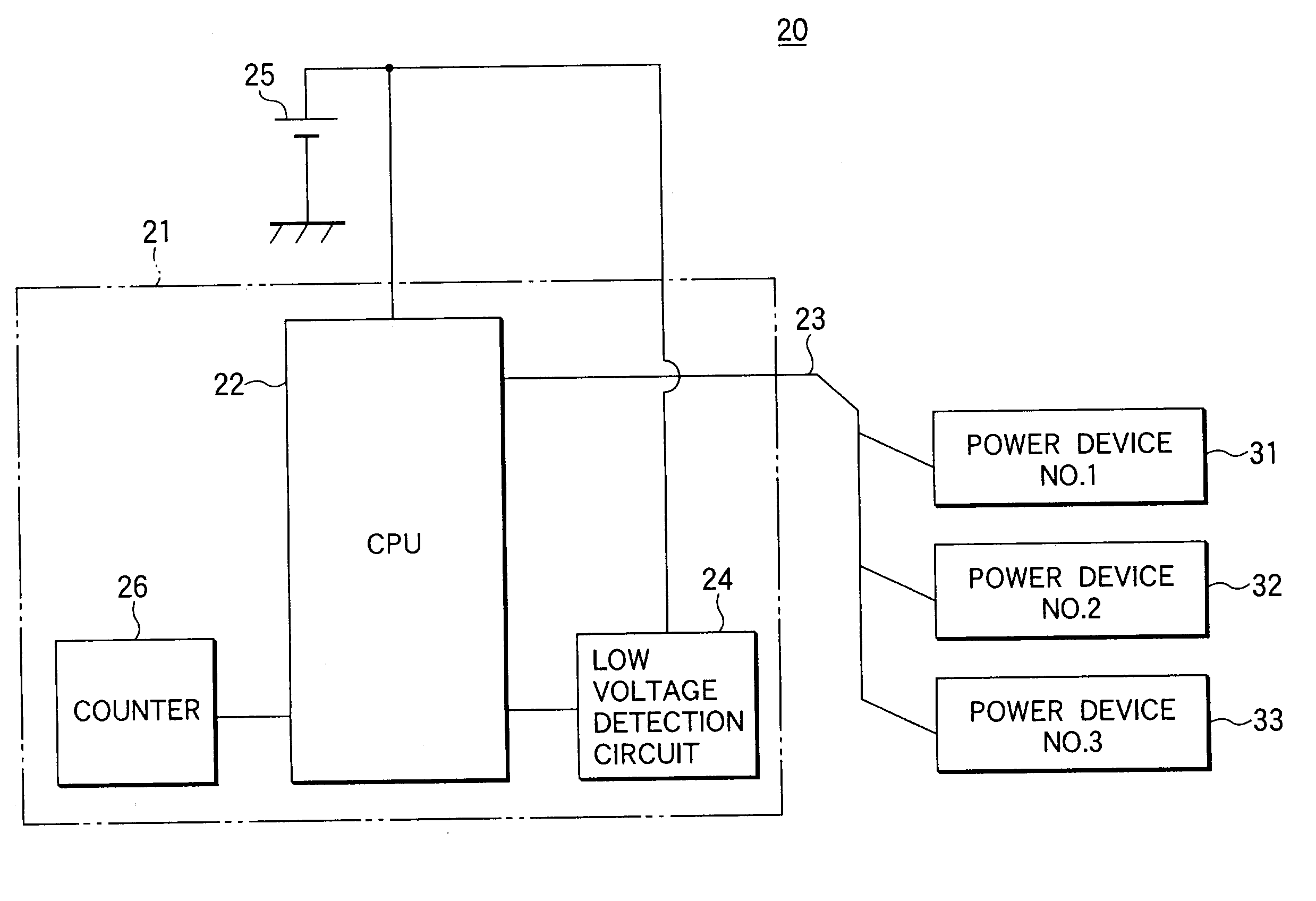
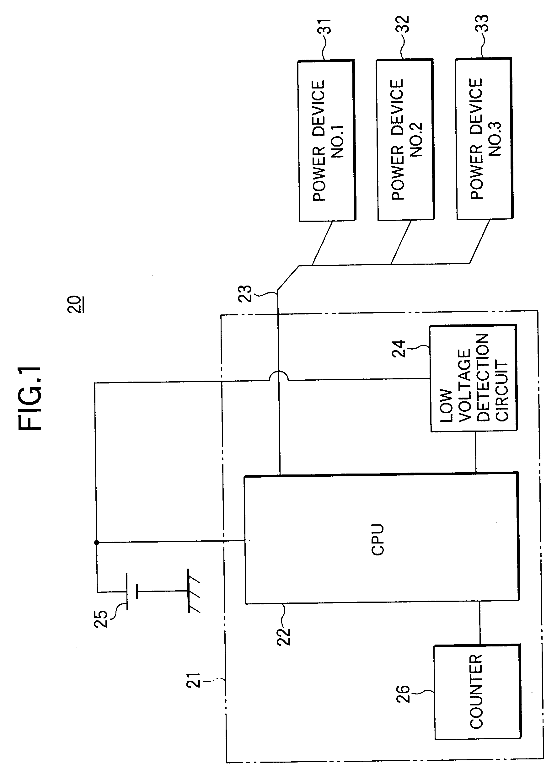
[0033]FIG. 1 shows a schematic electrical configuration of an electronic control system 20 according to the invention. This electronic control system 20 is mounted in, for example, an automobile, and performs various control. A CPU 22 of a control apparatus 21 performs processing for the control according to a program preset in a ROM (not shown) According to a control result, data for driving various actuators is sent and received by serial communication through a communication line 23. Since the serial communication is used, a configuration of the communication line 23 can be simplified. In the control apparatus 21, a drop in power source voltage is detected as a disturbance factor having an influence on the control. The drop in power source voltage is detected by a low-voltage detection circuit 24. In this embodiment, when a drop in voltage supplied from a power source such as a battery 25 is detected, the number of data received by the serial communication is counted by a counter...

second embodiment

[0038]FIG. 5 shows a schematic electrical configuration of an electronic control system 40 according to the invention. In this embodiment, the same reference numerals are attached to parts corresponding to the embodiment of FIG. 1 and overlap description is omitted. In the electronic control system 40 of the embodiment, a CPU 42 of a control apparatus 41 operates according to a preset program. A timer 45 is provided instead of the counter 26 of FIG. 1. When a drop in power source voltage is detected in a low-voltage detection circuit 24, constant time is set in the timer 45 and for a period of this time, self-diagnostic data by serial communication is ignored.

[0039]As shown in FIG. 6, in a manner similar to the embodiment of FIG. 1, data indicating the self-diagnostic result from three power devices 31, 32, 33 is sequentially received as a serial signal. During such self-diagnosis, when a power source voltage drops abnormally and becomes a low-voltage detection level or less, the lo...

third embodiment

[0042]FIG. 8 shows a schematic electrical configuration of an electronic control system 50 according to the invention. In this embodiment, the same reference numerals are attached to parts corresponding to the embodiment of FIG. 1 or FIG. 5 and overlap description is omitted. In the electronic control system 50 of the embodiment, a CPU 52 of a control apparatus 51 operates according to a preset program. Two low-voltage detection circuits 54, 55 are provided instead of the low-voltage detection circuit 24 of FIGS. 1 and 5. It is constructed so that different low-voltage detection levels are set in the two low-voltage detection circuits 54, 55 and different constant time is set in a timer 45 when each of the detection circuits detects a drop in power source voltage.

[0043]As shown in FIG. 9, in a manner similar to the embodiments of FIGS. 1 and 5, data indicating the self-diagnostic result from three power devices 31, 32, 33 is sequentially received as a serial signal. During such self...


PUM


Abstract

A control apparatus to which plural power devices are connected via a communication line. The power devices send data indicating a self-diagnostic result to the control apparatus by serial communications via the communication line. A CPU ignores serial communication data when a low-voltage detection circuit detects an abnormal drop in power source voltage. A period for ignoring data is set to time at which a completion of serial communication with all the power devices is determined by counting the number of communications by a counter. Even in case where an influence by the drop in power source voltage remains after recovery of the power source voltage due to communication delay, data that may includes abnormality is ignored and only self-diagnostic data with high reliability is used.

Description

[0001]The present disclosure relates to the subject matter contained in Japanese Patent Application No. 2001-356136 filed Nov. 21, 2001, which is incorporated herein by reference in its entirety.BACKGROUND OF THE INVENTION[0002]1. Field of the Invention[0003]The present invention relates to a control apparatus for conducting serial communication with a plurality of electronic devices thereby constitutes an electronic control system, and a self-diagnostic method in the electronic control system.[0004]2. Description of the Related Art[0005]Conventionally, a configuration as shown in FIG. 11 is used in various control. In a field so-called mechatronics, for example, a plurality of power devices 1, 2, 3 of No.1 to No.3 are used for driving various actuators by electronic control. Each power device 1, 2, 3 can pass a current to a motor or a solenoid to generate driving force, or pass a current to a heater to generate heat. Such an electronic control system 10 is controlled by a program o...

Claims


Application Information

Patent Timeline
Patent Type & Authority Patents(United States)
IPC IPC(8): G06F11/00G06F11/30G05B23/02H04Q9/00
CPCG05B23/0291G05B23/02
Inventor KOMIYA, MOTOKI
Owner FUJITSU GENERAL LTD
Why Eureka
Try Eureka