Laying apparatus for cables, lines, conductors or suchlike, and relative laying method

a technology of laying apparatus and conductor, which is applied in the direction of cable laying vessel, pipe laying vessel, coupling, etc., can solve the problems of hydraulic apparatus, difficult laying operation, and dangerous application of traction force, so as to reduce the working pressure inside the hydraulic circuit and limit the risk of oil temperature rising

Inactive Publication Date: 2006-08-22
TESMEC
View PDF17 Cites 27 Cited by
  • Summary
  • Abstract
  • Description
  • Claims
  • Application Information

AI Technical Summary

Benefits of technology

[0019]In a second form of embodiment, the detection means and the valve means are of the hydraulic type and comprise at least an adjustable valve able to intervene on the command members of the pump in order to reduce the delivery thereof and consequently reduce the pressure of the oil circulating in the circuit.
[0021]With the apparatus according to the present invention, it is therefore possible to reduce the working pressure inside the hydraulic circuit without performing any bypass of the oil circulation, since the valve means act directly on the delivery of the feed pump of the circuit.
[0022]Such solution considerably limits the risk of the temperature of the oil rising due to the effect of blow-bys in the pipes, during the steps when the pressure is reduced along the circuit.
[0023]Moreover, in the event that the laying apparatus according to the invention is associated with machines that can be used both in active steps of winch drawing, and passive steps of braking reaction, it makes these machines suitable for a predominantly automatic use with respect to the initial contrary manual maneuvers that may be carried out.

Problems solved by technology

It is known that for the installation of cables, for example for telephones, railroads, high or low tension, for fiber optic communication or otherwise, arranged aerial or underground, considerable traction forces are required which may be dangerous to apply due to the accidental obstacles that can increase the normal sliding friction.
Laying operations are particularly difficult in the case of stringing cables on long-distance electric power lines.
Such known hydraulic apparatuses have a main disadvantage, however, which is that they have a hydraulic plant regulated only by a so-called “limit valve”.
Such valve makes the oil re-circulate, bypassing the pump, when the working pressure in the circuit exceeds a pre-determined value which entails excessive, or in any case dangerous, traction of the cable, due to the resistance of the structure of the latter.
Therefore, in the event of a sudden and accidental obstacle to the sliding, due for example to a guide pulley seizing, the hydraulic motor slows down and therefore there is a rise in the hydraulic pressure.
Such increase in pressure is discharged onto the hydraulic motor, which thus exerts very high and dangerous traction, which can even lead to breakage of or damage to the cable being drawn.
Such transformation entails an overheating of the oil, however, causing it to almost totally lose its lubrication characteristics, and damaging the rubber or plastic parts, which are sensitive to heat.

Method used


Image

  • Laying apparatus for cables, lines, conductors or suchlike, and relative laying method
  • Laying apparatus for cables, lines, conductors or suchlike, and relative laying method
  • Laying apparatus for cables, lines, conductors or suchlike, and relative laying method

Examples


Embodiment Construction

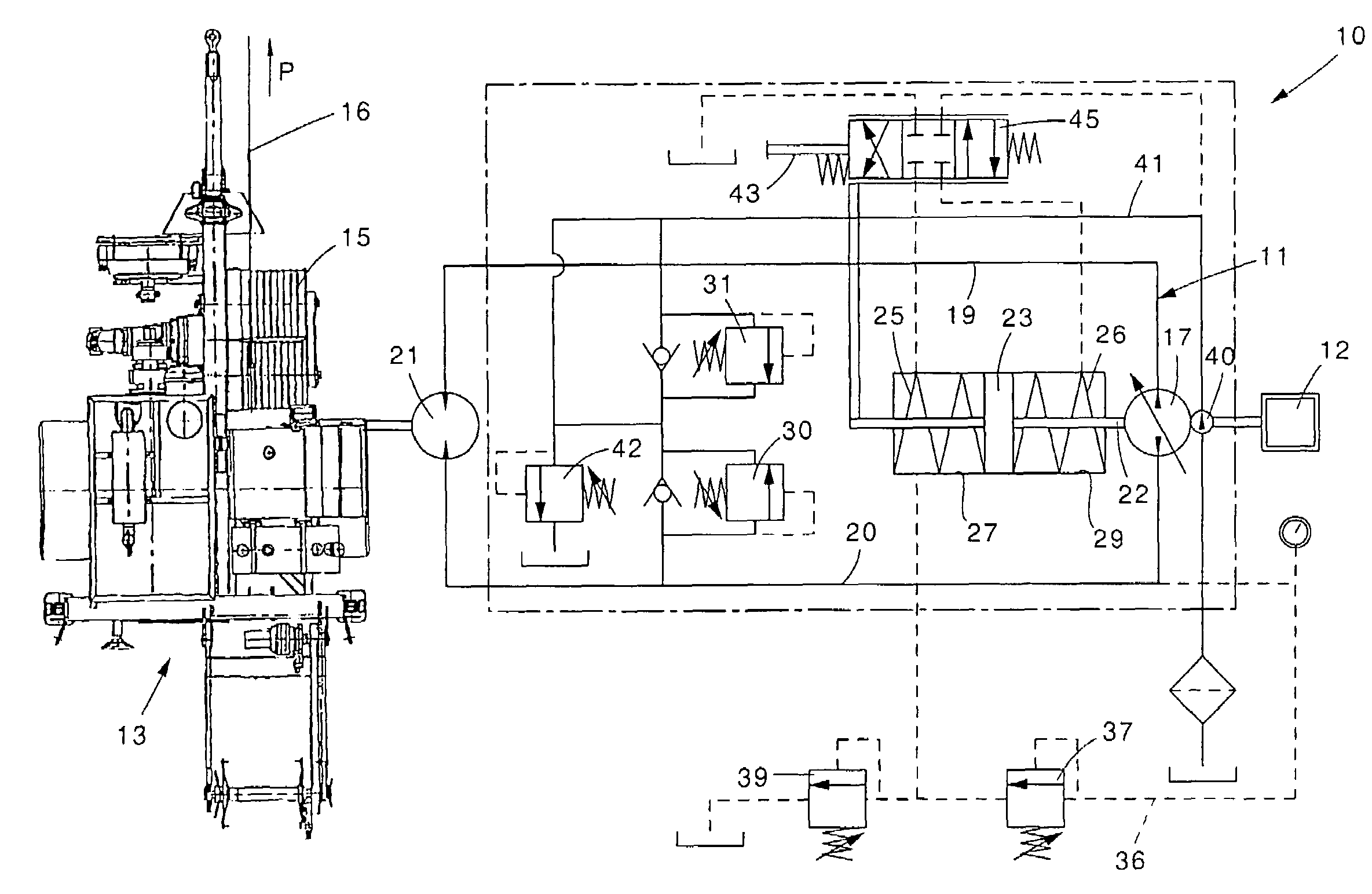
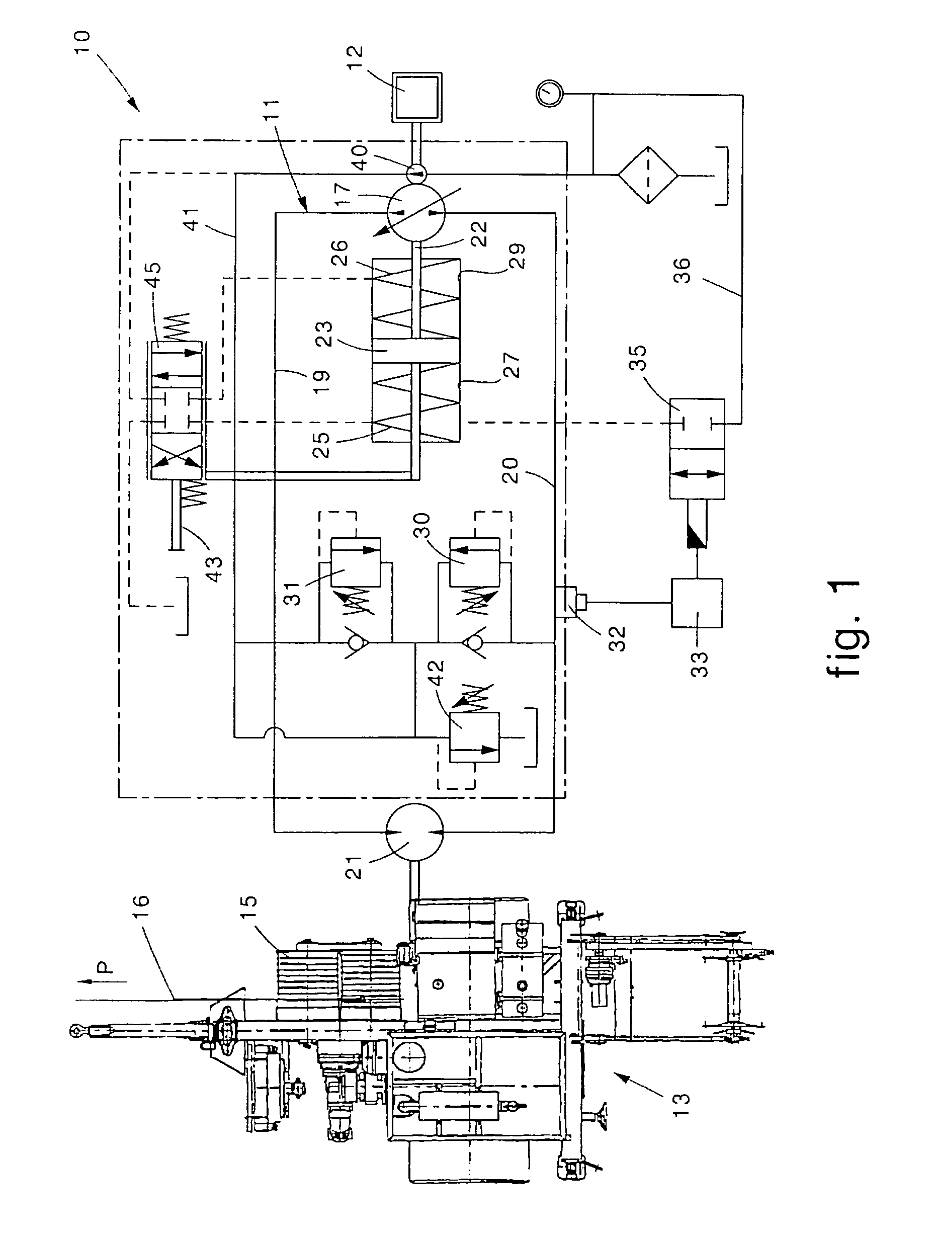
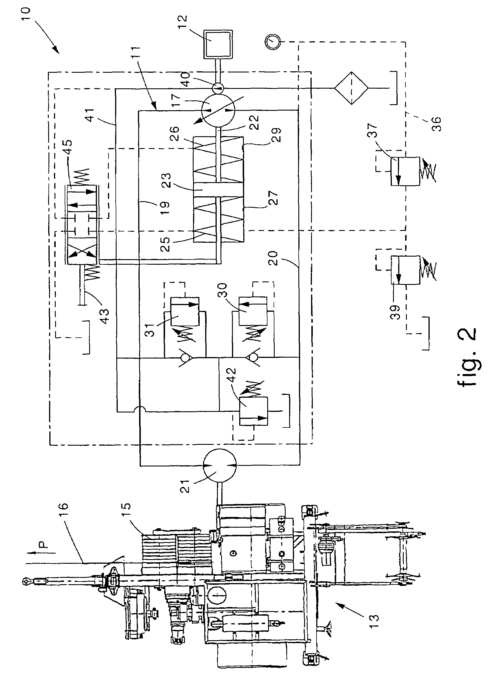
[0029]With reference to the attached drawings, an apparatus 10 according to the present invention comprises a hydraulic circuit 11 activated by a thermal motor 12.

[0030]In this case, the apparatus 10 according to the invention is associated with a winch 13 provided with a reel 15 for unwinding and / or braking an electric cable 16.

[0031]The hydraulic circuit 11 comprises a variable delivery pump 17, mechanically connected to the thermal motor 12, two main pipes 19 and 20, of which one is a delivery pipe and one is a return pipe, and a hydraulic motor 21 connected to the winch 13 to determine the rotation of the reel 15.

[0032]To prevent phenomena of cavitation and sudden variations in pressure, there is a small feed pump or preloading pump 40 advantageously present, inserted in the hydraulic circuit 11 by means of a specific pipe 41 and regulated by means of its own regulation valve 42.

[0033]The hydraulic circuit 11 thus defined is of a symmetric type, and for the description of its fu...


PUM


Abstract

Laying apparatus and method for cables, lines, conductors or suchlike. The apparatus comprises at least a hydraulic circuit provided with a variable delivery feed pump and with a motor connected to the feed pump in order to drive laying members for the cables and suchlike. The hydraulic circuit comprises detectors able to detect the value of pressure of the oil inside the hydraulic circuit and to compare it with a pre-determined pressure value, and valves connected to the detectors and able to reduce the delivery of the feed pump in the event that the pressure measured exceeds the pre-determined pressure value.

Description

FIELD OF THE INVENTION[0001]The present invention concerns an laying apparatus for cables, lines, conductors of long-distance electric power lines, cables with fiber optics, and more in general for any type whatsoever of electric cable, either aerial or underground, of any nature whatsoever, including those for the electrification of railroads.[0002]The present invention also concerns the method enacted by the apparatus and the laying machine using such apparatus.BACKGROUND OF THE INVENTION[0003]It is known that for the installation of cables, for example for telephones, railroads, high or low tension, for fiber optic communication or otherwise, arranged aerial or underground, considerable traction forces are required which may be dangerous to apply due to the accidental obstacles that can increase the normal sliding friction.[0004]Laying operations are particularly difficult in the case of stringing cables on long-distance electric power lines.[0005]In order to effect such operatio...

Claims


Application Information

Patent Timeline
Patent Type & Authority Patents(United States)
IPC IPC(8): F16D31/02B63B35/03F15B11/05F16L1/00
CPCF15B11/055F15B2211/20523F15B2211/25F15B2211/20569F15B2211/20553
Inventor BELLUSCHI, ANTONIO
Owner TESMEC
Why Eureka
Try Eureka