Gas turbine apparatus

a gas turbine and apparatus technology, applied in mechanical apparatus, electric generator control, machines/engines, etc., can solve the problems of excessive temperature of gas turbine apparatuses and complicated circuit arrangements, and achieve the effect of simplifying circuit arrangements, maximizing generated electric power, and high processing speed

Inactive Publication Date: 2006-08-22
EBARA CORP
View PDF4 Cites 14 Cited by
  • Summary
  • Abstract
  • Description
  • Claims
  • Application Information

AI Technical Summary

Benefits of technology

[0009]The present invention has been made in view of the above drawbacks. It is, therefore, an object of the present invention to provide a gas turbine apparatus having a control system which can maximize generated ele...

Problems solved by technology

Thus, the temperature of the gas turbine apparatus may excessively be increased when the gas turbine apparatus starts to operate.
The conventional gas turbine ap...

Method used


Image

  • Gas turbine apparatus
  • Gas turbine apparatus
  • Gas turbine apparatus

Examples


Embodiment Construction

[0026]A gas turbine apparatus according to embodiments of the present invention will be described below with reference to FIGS. 1 through 5.

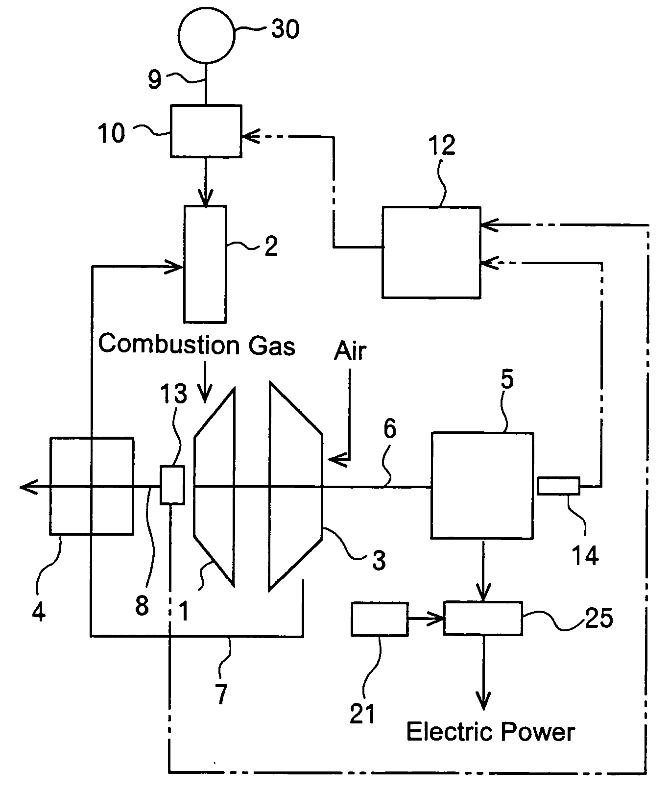
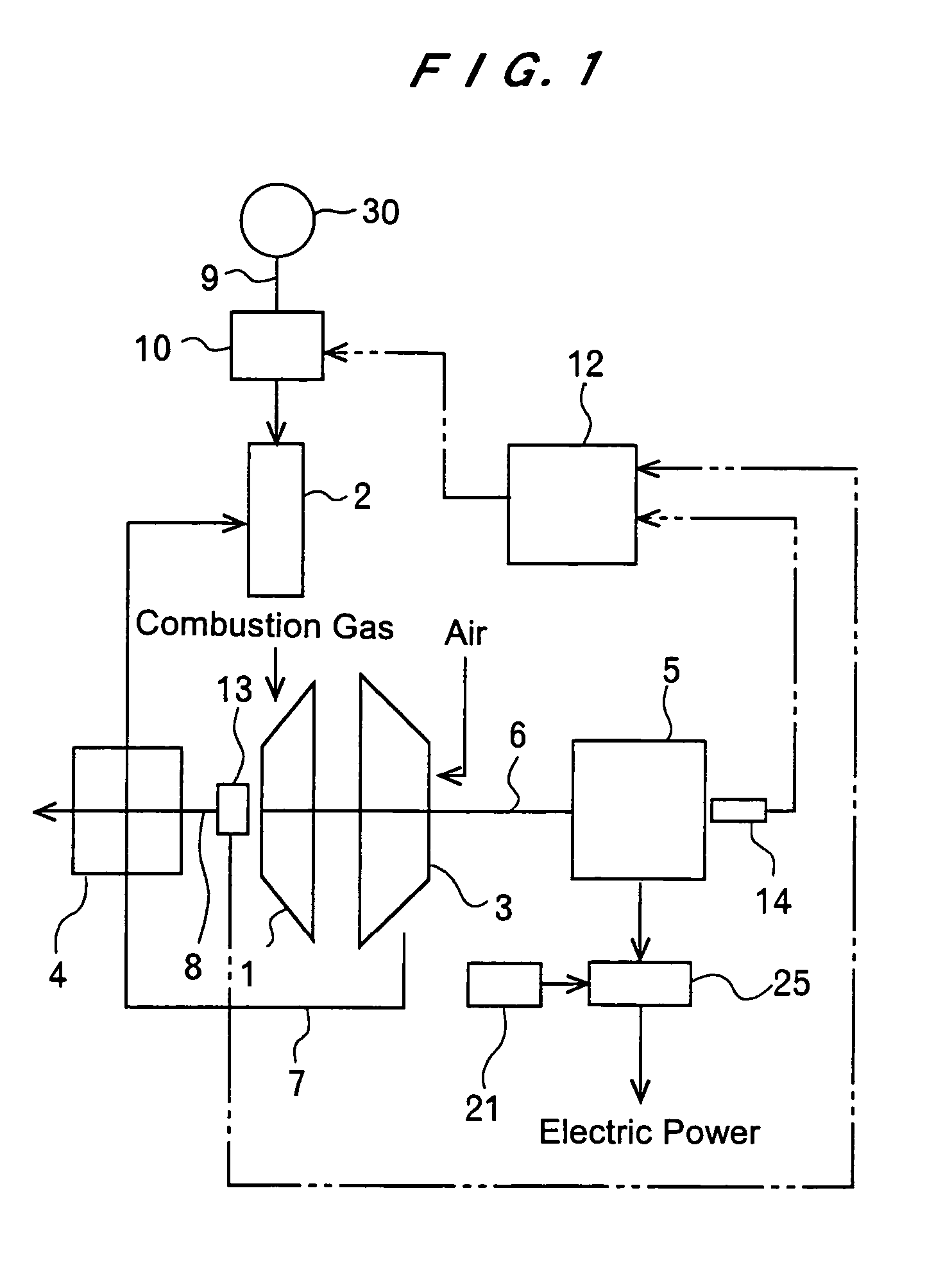
[0027]FIG. 1 is a block diagram showing an arrangement of a gas turbine apparatus according to a first embodiment of the present invention. As shown in FIG. 1, the gas turbine apparatus has a turbine 1, a combustor 2 for combusting a mixture of fuel and air to produce a combustion gas, a fuel flow control valve 10 for adjusting the amount of fuel to be supplied to the combustor 2, and an air compressor 3 for compressing air and supplying the compressed air to the combustor 2. The gas turbine apparatus also includes an electric generator 5 coupled to the turbine 1 and a turbine controller 12 for controlling the turbine 1 as a controlled system.

[0028]The turbine 1 is housed in a casing (not shown) and fixed to a rotational shaft 6. The rotational shaft 6 is rotatably supported by bearings (not shown) and can thus be rotated together with the turbi...


PUM


Abstract

A gas turbine apparatus has a combustor 2 for combusting fuel to produce a combustion gas, a turbine 1 which is rotated by the combustion gas, an electric generator 5 coupled to the turbine 1, and a fuel flow control valve 10 configured to change an opening thereof The gas turbine apparatus includes a first PID processing unit 16 to adjust the opening of the fuel flow control valve 10 so as to maintain a rotational speed of the turbine 1 substantially at a constant value, and a second PID processing unit 17 to adjust the opening of the fuel flow control valve 10 so as to maintain a temperature of a discharged combustion gas at temperatures lower than a predetermined temperature. The gas turbine apparatus has an electric power controller 21 to control electric power to be generated by the electric generator 5 based on output values of the first PID processing unit 16 and the second PID processing unit 17.

Description

BACKGROUND OF THE INVENTION[0001]1. Field of the Invention[0002]The present invention relates to a gas turbine apparatus, and more particularly to a gas turbine apparatus having a control system for controlling electric power generated by an electric generator based on the temperature of a discharged combustion gas. The present invention also relates to a method of controlling electric power generated by an electric generator in a gas turbine apparatus.[0003]2. Description of the Related Art[0004]Generally, a gas turbine apparatus has a turbine which is rotated by a fluid applied to the turbine, a combustor for combusting a mixture of fuel and air, a fuel flow control valve for adjusting the amount of fuel to be supplied to the combustor, and an air compressor for compressing air and supplying the compressed air to the combustor. The combustor produces a combustion gas having a high temperature and a high pressure when the mixture of fuel and air is combusted in the combustor. The c...

Claims


Application Information

Patent Timeline
IPC IPC(8): F02C9/28F01D15/10F02C9/32
CPCF01D15/10F02C9/28F02C9/32F05D2270/02F05D2270/54F05D2270/706F05D2270/303F05D2270/3032F05D2270/024F05D2270/053F05D2270/06F05D2270/304
Inventor MCKELVEY, TERENCEMARUI, EISHIMIYAMOTO, MASAHIROKATAOKA, TADASHIFURUYA, TAI
Owner EBARA CORP
Why Eureka
Try Eureka