Video display apparatus and video display method

a video display and video display technology, applied in the field of video display apparatus and video display method, can solve the problems of not being able to improve the display quality in each scene of the input video signal, the life of the light source is degraded, and the floating blackness is not mitigated for a dark scene. to achieve the effect of improving display quality and preventing the degrade of the light sour

Inactive Publication Date: 2006-08-22
PANASONIC CORP
View PDF25 Cites 36 Cited by
  • Summary
  • Abstract
  • Description
  • Claims
  • Application Information

AI Technical Summary

Benefits of technology

[0129]According to the above-mentioned forty-fifth aspect, it is possible to prevent the life of the light source from being degraded by continuing to change the brightness of the light source for a long time period. Particularly when the brightness of the light source changes in the intermediate state for not less than the predetermined time period, the control of the brightness of the light source is interrupted, thereby making it possible to interrupt the control of the brightness of the light source at a minimum essential while improving the display quality.

Problems solved by technology

However, the method of controlling the brightness of the light source which has been employed in the conventional direct view type liquid crystal display apparatus and projection type display apparatus is static fixed control and does not cope with the dynamic change in the input video signal, as described above.
Therefore, the display quality in each scene of the input video signal cannot be improved.
Therefore, floating blackness is not mitigated for a dark scene as in movie software.
Therefore, in an input scene where the maximum value is locally high or the minimum value is locally low, the features of the input scene cannot be entirely grasped, leading to an unsuitable control of the brightness of the light source.
Further, the brightness of the light source is discontinuously controlled.
Accordingly, the brightness of a screen is greatly changed at the time point where the brightness of the light source is changed, thereby giving an uncomfortable feeling to a viewer.
Further, a discharging light source, such as a xenon lamp or a high-pressure mercury lamp, employed for the projection type display apparatus repeats a rapid change in driving conditions to cause instability of lighting starting characteristics, and degradation in stable lighting characteristics and degradation in life characteristics, such as flicker at the time of stationary lighting, resulting in the degraded reliability of the lamp.

Method used


Image

  • Video display apparatus and video display method
  • Video display apparatus and video display method
  • Video display apparatus and video display method

Examples


first embodiment

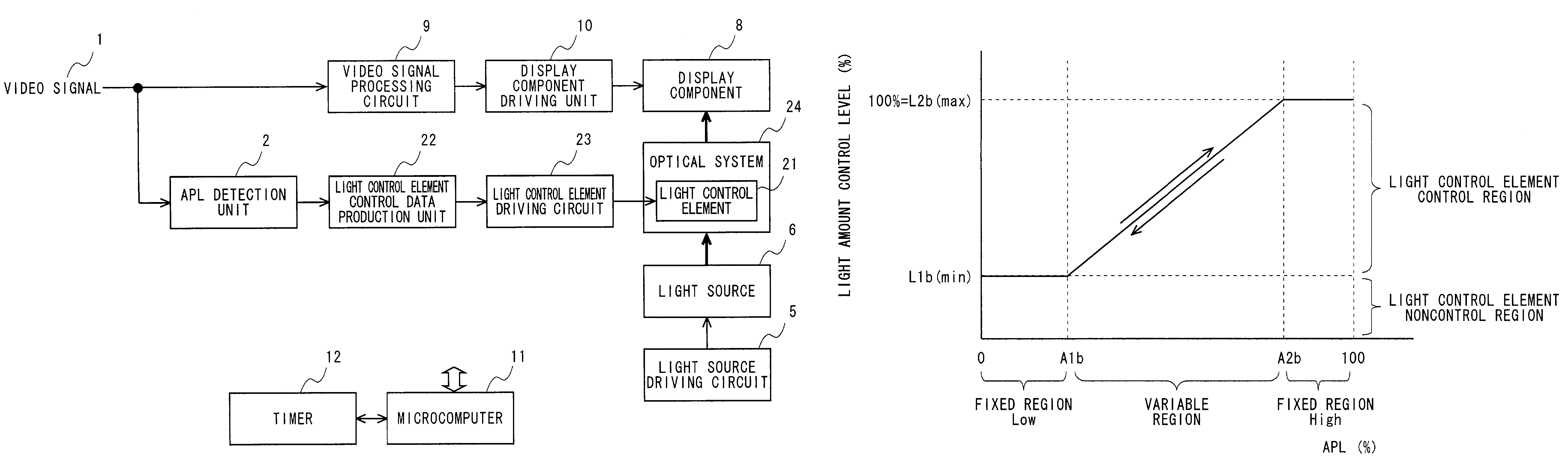
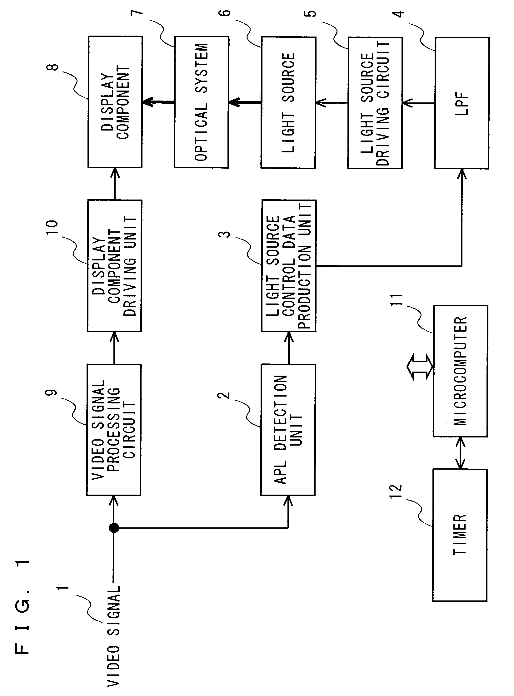
[0171]FIG. 1 illustrates the configuration of a video display apparatus according to a first embodiment of the present invention. The video display apparatus includes an APL detection unit 2, a light source control data production unit 3, an LPF 4, a light source driving circuit 5, a light source 6, an optical system 7, a display component 8, a video signal processing circuit 9, a display component driving unit 10, a microcomputer 11, and a timer 12. The optical system 7 is provided when the video display apparatus is a projector, and is not provided when it is of a direct view type. Operations in the first embodiment are described below.

[0172]A video signal 1 is fed to the video display apparatus. The video signal 1 is inputted to the video signal processing circuit 9 and the APL detection unit 2. The video signal 1 inputted to the video signal processing circuit 9 is subjected to signal processing required for a display apparatus, for example, contrast control and brightness contr...

second embodiment

[0215]FIG. 14 illustrates the configuration of a video display apparatus according to a second embodiment of the present invention. The video display apparatus includes an APL detection unit 2, a light source control data production unit 13, an LPF 4, a light source driving circuit 5, a light source 6, an optical system 7, a display component 8, a video signal processing circuit 9, a display component driving unit 10, a microcomputer 11, and a timer 12. The present embodiment differs from the first embodiment only in the operations of the light source control data production unit 13. Therefore, the same other components are assigned the same reference numerals and hence, the descriptions thereof are not repeated.

[0216]Referring to FIG. 15, the operation of the light source control data production unit 13 is described. The light source control data production unit 13 performs processing for relaxing the dynamic follow-up characteristics of light source level control to the change in ...

third embodiment

[0224]FIG. 18 illustrates the configuration of a video display apparatus according to a third embodiment of the present invention. The video display apparatus includes an APL detection unit 2, a light source control data production unit 14, an LPF 4, a light source driving circuit 5, a light source 6, an optical system 7, a display component 8, a video signal processing circuit 9, a display component driving unit 10, a microcomputer 11, and a timer 12. The present embodiment differs from the first embodiment only in the operations of the light source control data production unit 14. Therefore, the same other components are assigned the same reference numerals and hence, the descriptions thereof are not repeated.

[0225]Referring to FIG. 19, the operations of the light source control data production unit 14 are described. The light source control data production unit 14 performs processing for relaxing the dynamic follow-up characteristics of light source level control to the change in...


PUM

PropertyMeasurementUnit
time constantaaaaaaaaaa
transmissionaaaaaaaaaa
reflectionaaaaaaaaaa

Abstract

An APL detection unit detects the APL for each unit field time period of an input video signal, and a light source control data production unit produces, depending on the results of the APL detection, a light source control signal at a minimum level which can stably drive a light source when the APL is 0% up to a predetermined value A1, a light source control signal at a maximum level which can stably drive the light source when the APL is a predetermined value A2 up to 100%, and a light source control signal which dynamically varies depending on the APL when the APL is between the predetermined value A1 and the predetermined value A2, to drive the light source on the basis of the light source control signal. As a result, it is possible to mitigate the lack of a contrast feeling and the occurrence of a floating blackness, as well as to improve the reliability of the light source.

Description

TECHNICAL FIELD[0001]The present invention relates to a video display apparatus and a video display method, and more particularly, to a video display apparatus and a video display method, in which light from a light source is irradiated onto a transmission type or reflection type display component having a light modulating function to display video.BACKGROUND ART[0002]In recent years, with enhancement of video equipment, such as a video tape recorder or a video disk player and video software, desires for image display apparatuses capable of enjoying powerful video have increased.[0003]Examples of video display apparatuses for spatially modulating light emitted from a light source by a transmission type or reflection type display component having a light modulating function to display video include a direct view type liquid crystal display apparatus and a projection type display apparatus. In the direct view type liquid crystal display apparatus, a liquid crystal panel is used for th...

Claims


Application Information

Patent Timeline
Patent Type & Authority Patents(United States)
IPC IPC(8): G03B21/20G02F1/13357G09G3/34G09G3/36G09G5/10H04N5/57H04N5/74
CPCG09G3/3406H04N21/44008H04N5/74G09G3/36G09G5/10G09G2320/0633G09G2320/0653G09G2360/16H04N5/57H04N21/4318G09G2320/066
Inventor KAWASHIMA, MASAHIRONODA, HITOSHIGYOTEN, TAKAAKI
Owner PANASONIC CORP
Why Eureka
Try Eureka