
Master information carrier for magnetic transfer and magnetic transfer method

a technology of information carrier and magnetic transfer, applied in the direction of maintaining head carrier alignment, nanoinformatics, instruments, etc., can solve the problems of deteriorating productivity, short time required for preformat recording, and partial loss of magnetic layer or pattern, etc., to achieve excellent reproduction signal and improve durability

Inactive Publication Date: 2006-08-22
FUJIFILM CORP
View PDF11 Cites 2 Cited by
  • Summary
  • Abstract
  • Description
  • Claims
  • Application Information

AI Technical Summary

Benefits of technology

The improved master information carrier enhances durability, allowing for higher-quality signal reproduction and increased production efficiency by reducing the need for frequent replacements, thereby lowering production costs and maintaining signal integrity.

Problems solved by technology

However, the preformat recording by the conventional servo recording apparatus is disadvantageous in that it takes a long time since the servo information must be recorded on the magnetic recording medium one by one by the use of a magnetic head, which deteriorates the productivity.
Thus, according to the magnetic transfer, the preformat recording can be performed accurately and the time required for the preformat recording is very short.
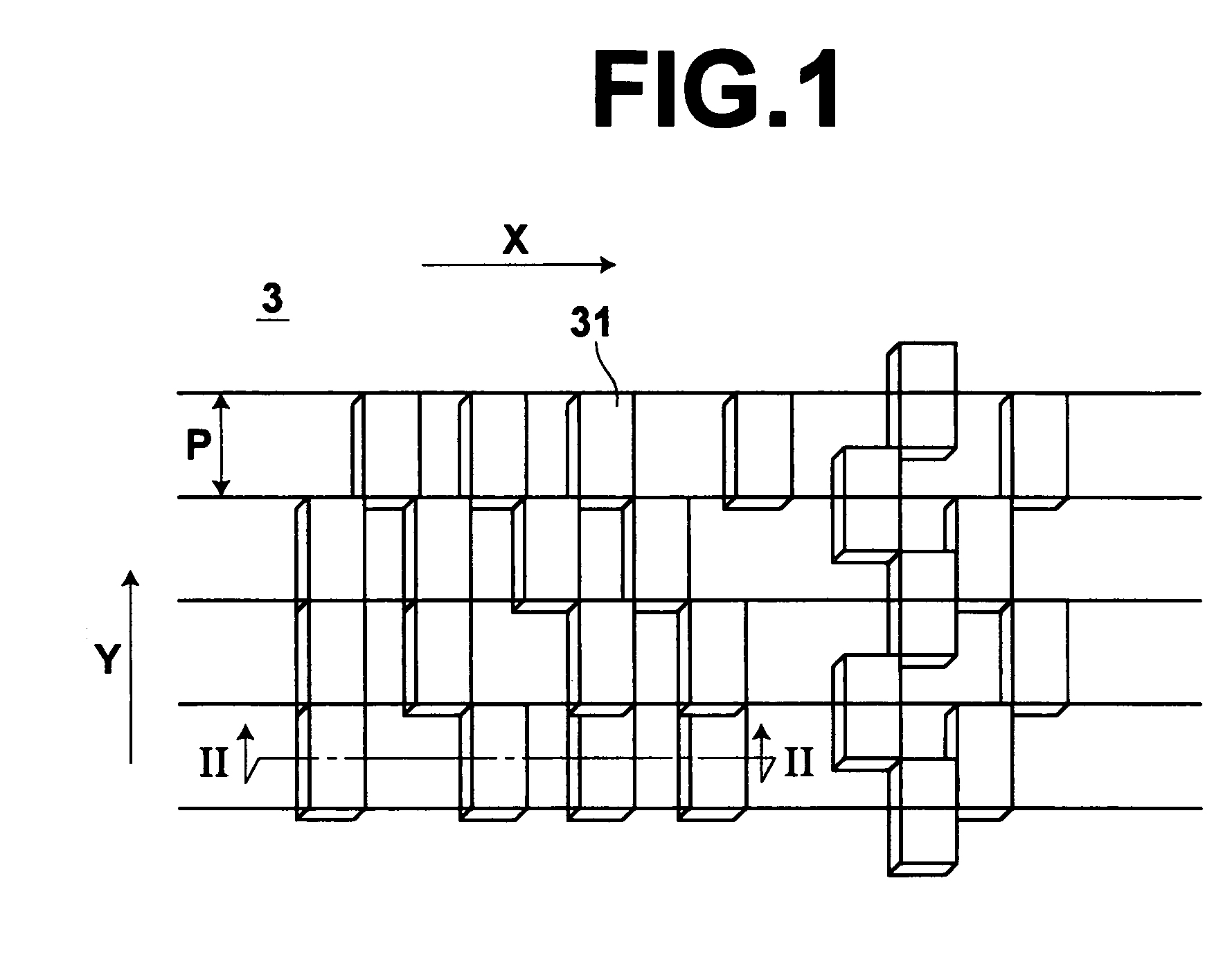
However, the master information carrier employed in the magnetic transfer disclosed in above identified Japanese Unexamined Patent Publications comprises a base sheet having on the surface thereof an irregularity pattern representing the information to be transferred and a magnetic layer formed at least on the surface of the protruding portions of the base sheet and since the magnetic transfer is carried out with the master information carrier and the slave medium held in close contact with each other, the magnetic layer can be partly lost or peeled off the pattern while the master information carrier is repeatedly brought into contact with and moved away from a number of slave media.
Removal of the magnetic layer from the master information carrier deteriorates contact between the master information carrier and the slave medium, which can result in deterioration in quality of the transferred signal.
The master information carrier is expensive and how many slave media can be made per one master information carrier largely governs the production cost of a magnetic recording medium.
That is, it was presumed that dynamic structural weakness of the master information carrier caused the magnetic layer to be peeled off.
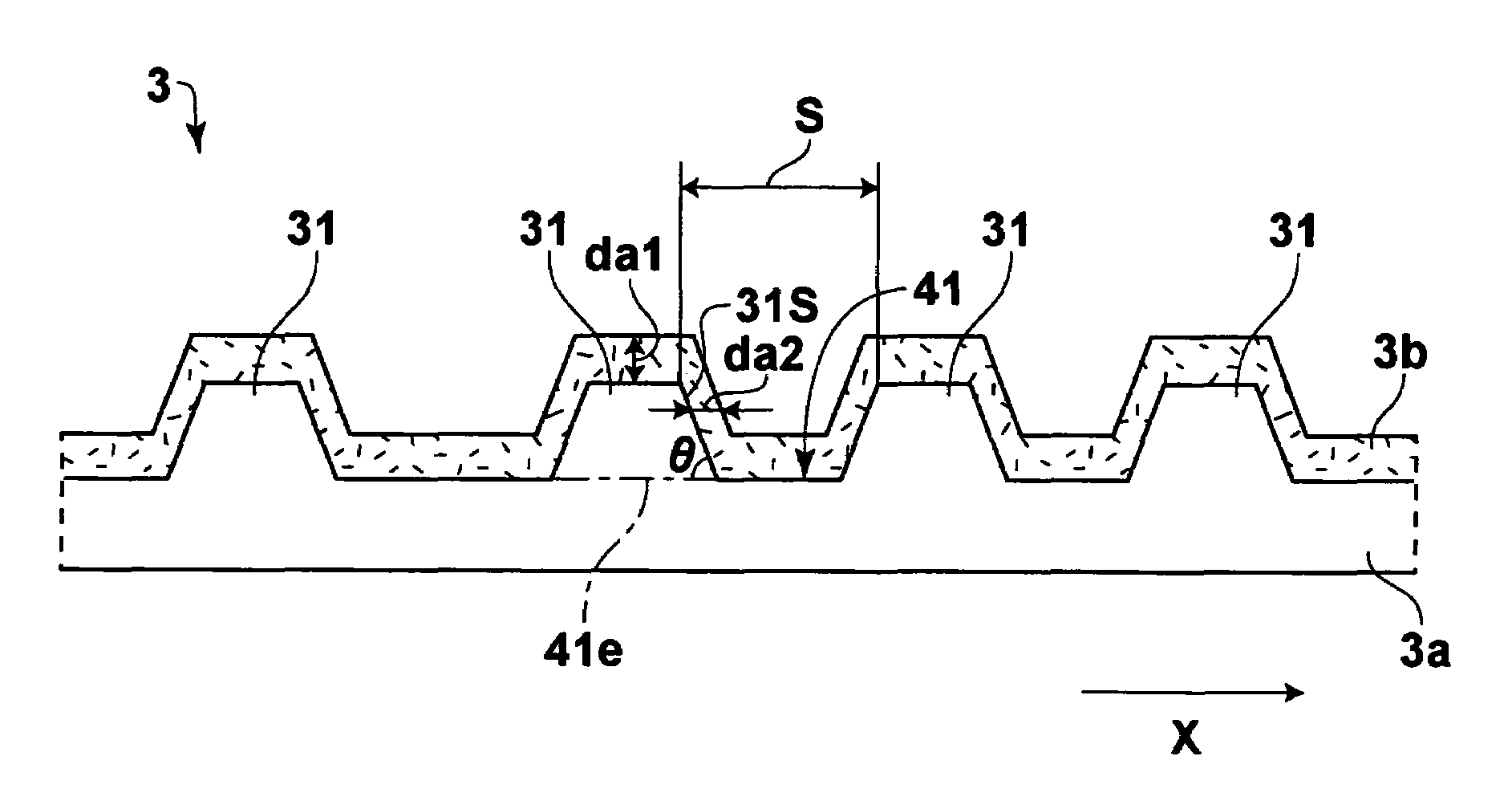
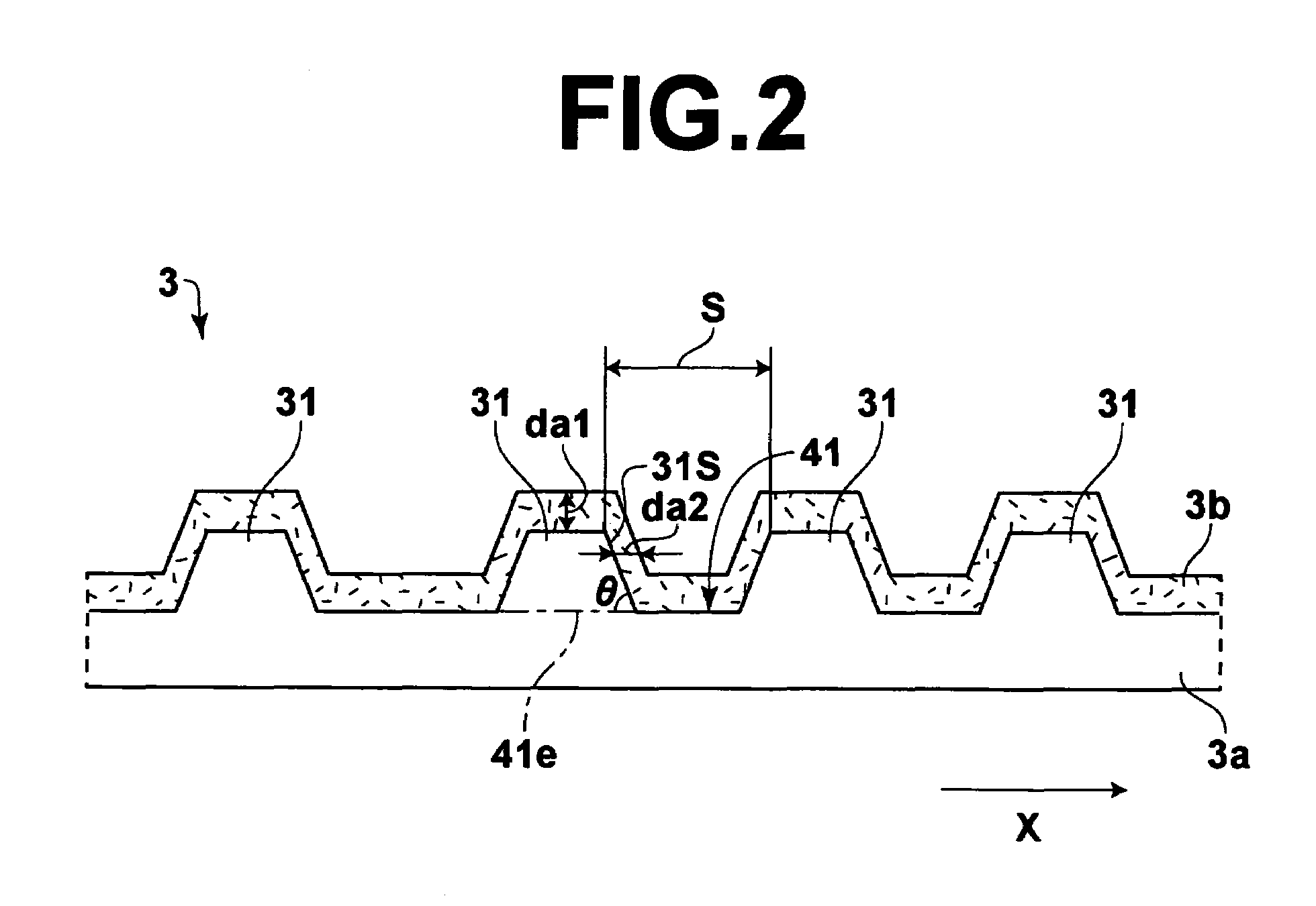
Further, our investigation has revealed that the thickness of the magnetic layer on the side faces of the protruding portions of the irregularity pattern on the master information carrier largely affects the quality of the signal transferred to the slave media.

Method used


Image

  • Master information carrier for magnetic transfer and magnetic transfer method
  • Master information carrier for magnetic transfer and magnetic transfer method
  • Master information carrier for magnetic transfer and magnetic transfer method

Examples


examples

[0072]Master information carriers in accordance with first to twenty-second embodiments of the present invention and first to fourth comparative examples were made in the following way and transferred signal quality and durability of the master information carriers were evaluated in the following manner. The result is shown in the following table. In the table, “emb” is “embodiment”, “c / e” is an abbreviation of “comparative example”, “SQ” is an abbreviation of “transferred signal quality”, and “dur” is an abbreviation of “durability”.

Evaluation of the Transferred Signal Quality

[0073]Quality of the signal reproduced from the slave medium was evaluated by the use of electromagnetic conversion property meter (SS-60: KYODO Electronics). A GMR head which was 0.12 μm in reproducing head gap, 0.41 μm in reproducing track width, 0.2 μm in recording head gap and 0.67 μm in recording track width was employed. The read signal was divided into frequencies by a spectro-analyzer, and the differen...

third embodiment

[0079]The information on the master information carrier were transferred to the slave media in the same manner as in the first embodiment except that da2 / da1 was changed to 1.3.

fourth embodiment

[0080]The information on the master information carrier were transferred to the slave media in the same manner as in the first embodiment except that da2 / S was changed to 0.09.


PUM

PropertyMeasurementUnit
angleaaaaaaaaaa
angleaaaaaaaaaa
thicknessaaaaaaaaaa

Abstract

A master information carrier for magnetic transfer to an in-plane magnetic recording medium includes a base sheet having an irregularity pattern representing information to be transferred to an in-plane magnetic recording medium and a magnetic layer formed along the irregularity pattern. The thickness da 1 of the magnetic layer on the upper surface of a protruding portion of the irregularity pattern and the thickness da 2 of the magnetic layer on each of the side surfaces of the protruding portion satisfy the following condition, <?in-line-formulae description="In-line Formulae" end="lead"?>0.05<da2 / da1<=1.3.<?in-line-formulae description="In-line Formulae" end="tail"?>

Description

[0001]This is a divisional of application Ser. No. 10 / 304,998 filed Nov. 27, 2002 now U.S. Pat. No. 6,816,327.BACKGROUND OF THE INVENTION[0002]1. Field of the Invention[0003]This invention relates to a master information carrier carrying thereon an irregularity pattern representing the information to be transferred to a magnetic medium and a magnetic transfer method.[0004]2. Description of the Related Art[0005]With an increase in information quantity, there is a demand for a magnetic recording medium which is high in memory capacity, low in cost and preferably requires a short time to read out a necessary part of data (a magnetic recording medium which allows so-called high-speed access). As an example of such a magnetic recording medium, there has been known a high recording density magnetic medium such as a hard disc, a zip (Iomega) and the like. In such a high recording density magnetic medium, the recording area is formed by narrow data tracks. In order to cause a magnetic head ...

Claims


Application Information

Patent Timeline
Patent Type & Authority Patents(United States)
IPC IPC(8): G11B5/64G11B5/86G11B5/596G11B5/82
CPCB82Y10/00G11B5/865G11B5/743G11B5/59633Y10T428/273G11B5/82G11B5/86
Inventor NISHIKAWA, MASAKAZUNIITSUMA, KAZUHIROYASUNAGA, TADASHIUSA, TOSHIHIROKOMATSU, KAZUNORI
Owner FUJIFILM CORP
Learn More