Monitoring device, electrical machine tool, current supply device, and associated method of operation

a current supply device and monitoring device technology, applied in the direction of motor/generator/converter stopper, dynamo-electric converter control, instruments, etc., can solve the problems of not monitoring the operating temperature, damage to the electrical machining tool or the accumulator that serves to supply the current, etc., to prevent damage to the electrical machining tool or the associated current supply device, shorten the life of the accumulator

Inactive Publication Date: 2006-08-22
ROBERT BOSCH GMBH
View PDF14 Cites 18 Cited by
  • Summary
  • Abstract
  • Description
  • Claims
  • Application Information

AI Technical Summary

Benefits of technology

[0016]So, as a rule, a switching off takes place, when the monitored operating parameter exceeds the specified maximum value, in order to prevent damage of the electrical machining tool or the associated current supply device. Preferably, the electrical machining tool, then, is also automatically switched off, if the monitored operating parameter falls below the specified minimal value, since, for example, a discharge of a very cold accumulator shortens the longevity of the accumulator.

Problems solved by technology

With today's electrical machining tools, such as, for example, hand drills and accumulator worms, the operating temperature is not monitored, which is problematic in two different views.
For one, exceeding of an apparatus-specific maximum temperature can lead to damage of the electrical machining tool or of the accumulator that serves to supply the current, which must be observed by the respective user, in particular, with a heavy mechanical load of the electrical machining tool.

Method used


Image

  • Monitoring device, electrical machine tool, current supply device, and associated method of operation
  • Monitoring device, electrical machine tool, current supply device, and associated method of operation
  • Monitoring device, electrical machine tool, current supply device, and associated method of operation

Examples


Embodiment Construction

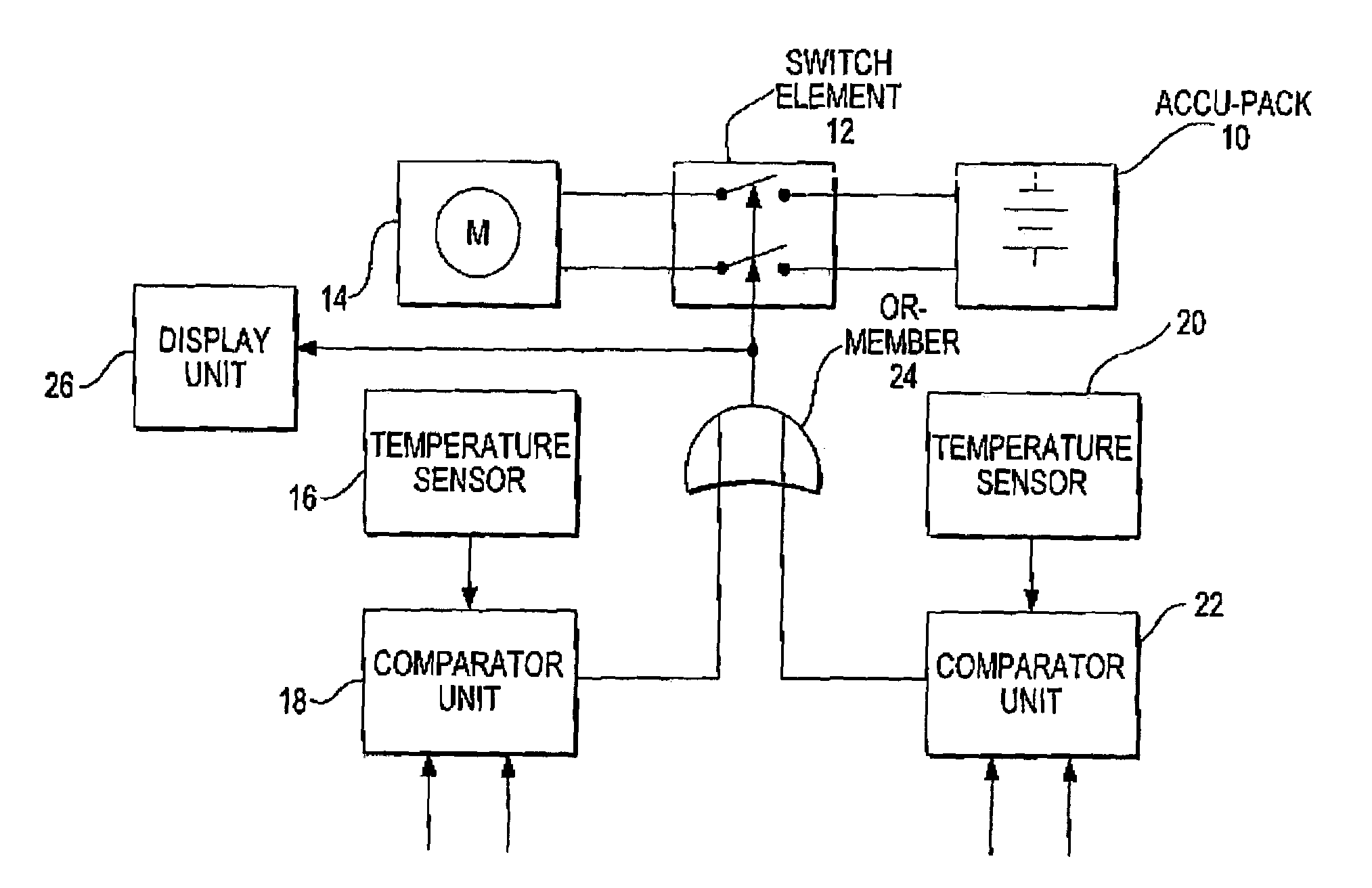
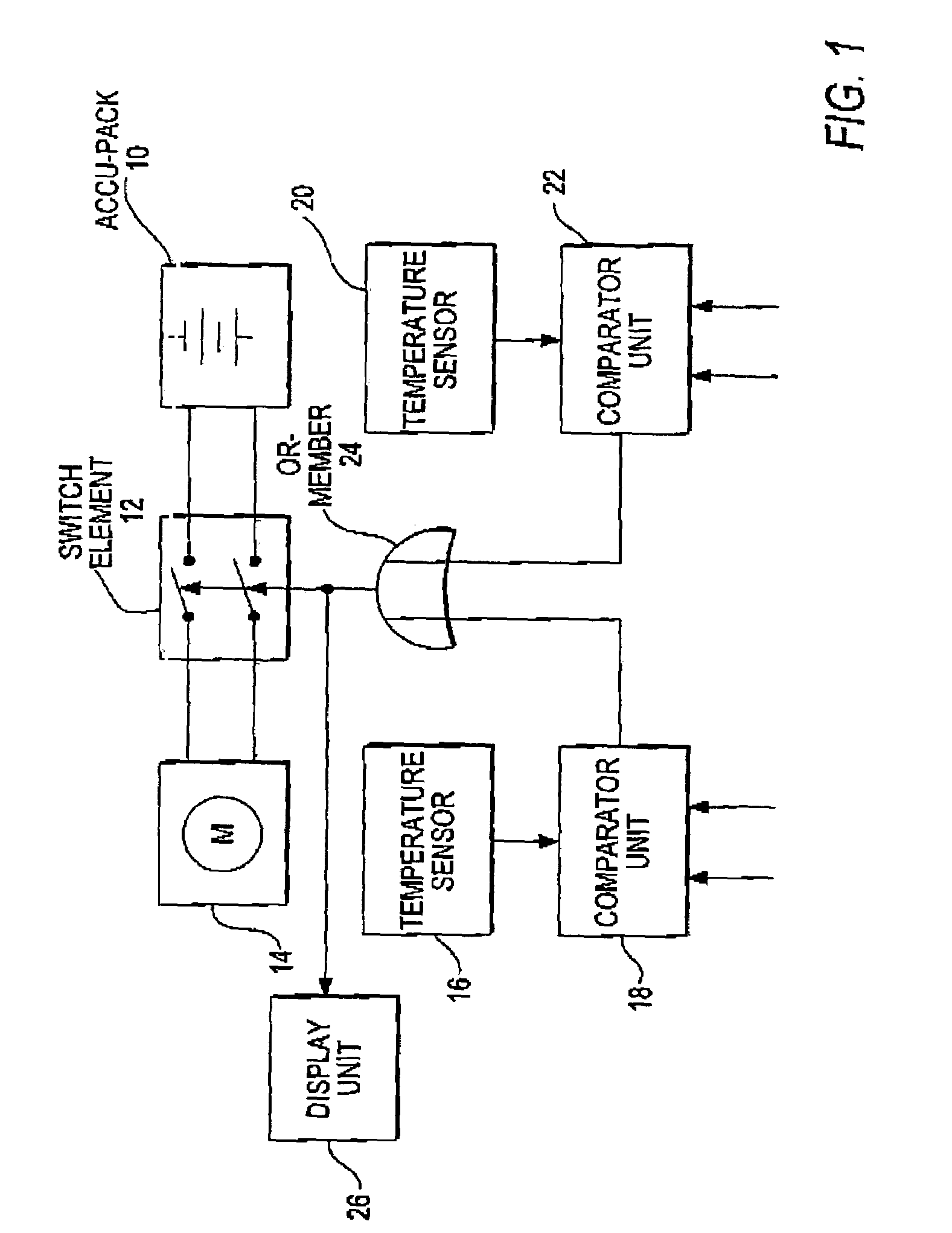
[0029]The embodiment represented in FIG. 1 serves for monitoring the temperature of a hand-held machining tool, whereby, for example, the machining tool can operate as accumulator-driven hand drill.

[0030]The current supply takes place by means of an accumulator pack (“accu-pack”) 10, which is connected with an electric motor 14 that drives the hand-held machining tool via a controllable switch element 12. In addition, the hand-held machining tool has an electronic control and operating elements, which for the sake of simplicity, are not illustrated.

[0031]For measurement of the operating temperature of the electrical motor 14, the hand-held machining tool has a temperature sensor 16, which emits a corresponding temperature signal TMOTOR on the output side.

[0032]On the output side, the temperature sensor 16 is connected with a comparator unit 18, which compares the actual operating temperature TMOTOR of the electrical motor 14 with a predetermined minimal value TMIN1 and a predetermin...


PUM


Abstract

A monitoring device for an electrical machining tool, in particular for temperature monitoring with an accumulator-driven machine, includes a switch element (12) for separating an electrical consumer (14) from a current supply device (10). For detection of a first operating parameter (TMOTOR) of the consumer (14) and/or the current supply device (10), a first sensor (16) is provided, whereby the first sensor (16) is connected with a display unit and/or with the control input of the switch element, in order to control the switching process as a function of the first operating parameter (TMOTOR). Furthermore, the present invention relates to an electrical machining tool as well as a current supply device with the inventive monitoring device and a corresponding method of operation.

Description

BACKGROUND OF THE INVENTION[0001]The present invention relates to monitoring device for an electrical machining tool, an electrical machining tool or a current supply device with the inventive monitoring device, as well as a corresponding method of operation.[0002]With today's electrical machining tools, such as, for example, hand drills and accumulator worms, the operating temperature is not monitored, which is problematic in two different views.[0003]For one, exceeding of an apparatus-specific maximum temperature can lead to damage of the electrical machining tool or of the accumulator that serves to supply the current, which must be observed by the respective user, in particular, with a heavy mechanical load of the electrical machining tool.[0004]For another, the longevity of an accumulator is reduced substantially, when the accumulator is discharged at very low temperatures. In particular, after a long storage period of an electrical machining tool in cold spaces, the accumulato...

Claims


Application Information

Patent Timeline
Patent Type & Authority Patents(United States)
IPC IPC(8): G01R31/02G01R31/14G05D23/00H03L7/00B25F5/00H02H7/085H02H11/00H02P7/06H02P29/00H02P29/02
CPCH02H7/0852H02H11/00
Inventor FIEBIG, ARNIMBAUR, HANS-JOACHIMLOHR, GUENTERROEPKE, STEFANGLAUNING, RAINERBOSCH, VOLKER
Owner ROBERT BOSCH GMBH
Why Eureka
Try Eureka