Optical distributor and optical distributing system

a technology of optical distributor and optical distributing system, which is applied in the direction of optical elements, electromagnetic repeaters, instruments, etc., can solve the problems of increasing wiring costs, unable to send enough optical signals to the light receiving unit of each receiver, and unable to meet the optical signal of sufficient level

Inactive Publication Date: 2006-08-22
FUJIFILM BUSINESS INNOVATION CORP
View PDF14 Cites 27 Cited by
  • Summary
  • Abstract
  • Description
  • Claims
  • Application Information

AI Technical Summary

Problems solved by technology

In this case, installed optical fibers equal in number to the receivers are required, resulting in increase of wiring cost.
Accordingly, it is impossible to send the optical signal of sufficient level

Method used


Image

  • Optical distributor and optical distributing system
  • Optical distributor and optical distributing system
  • Optical distributor and optical distributing system

Examples


Embodiment Construction

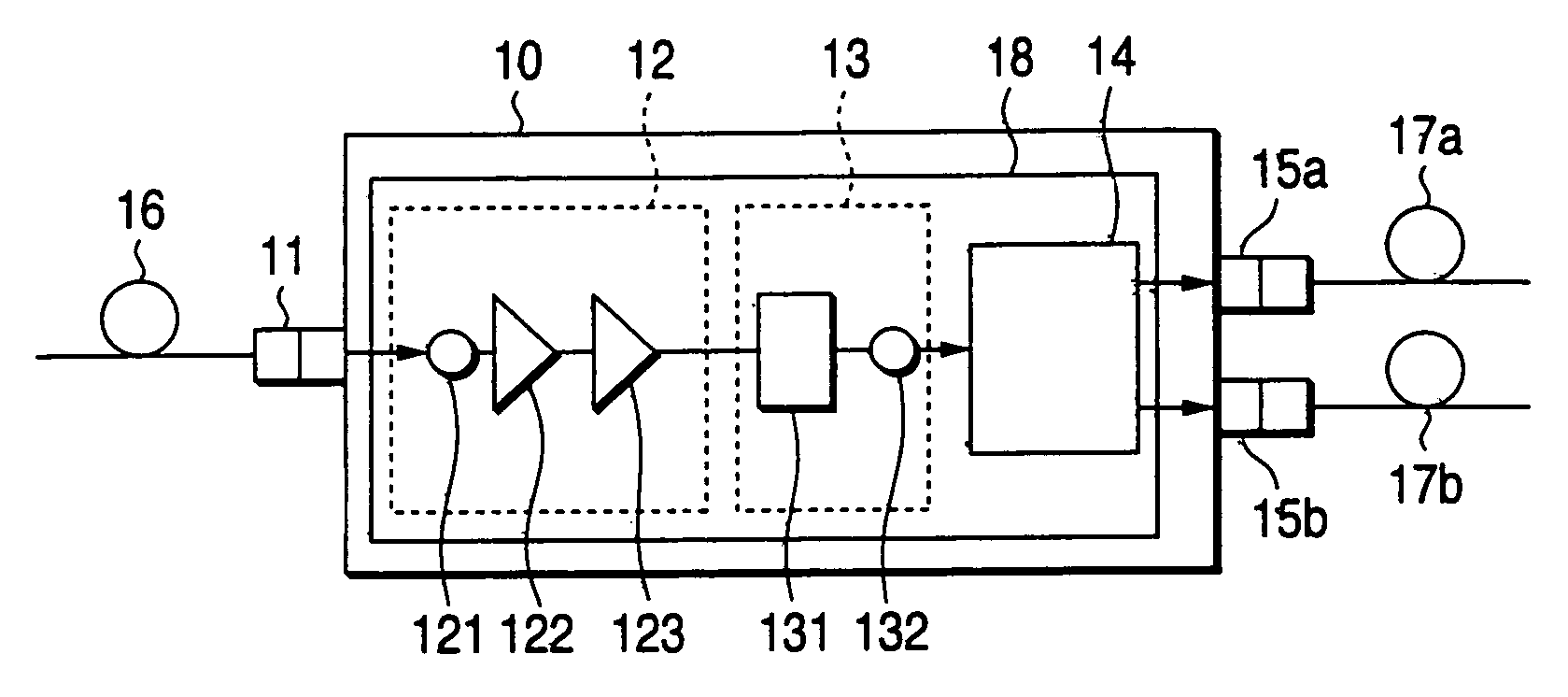
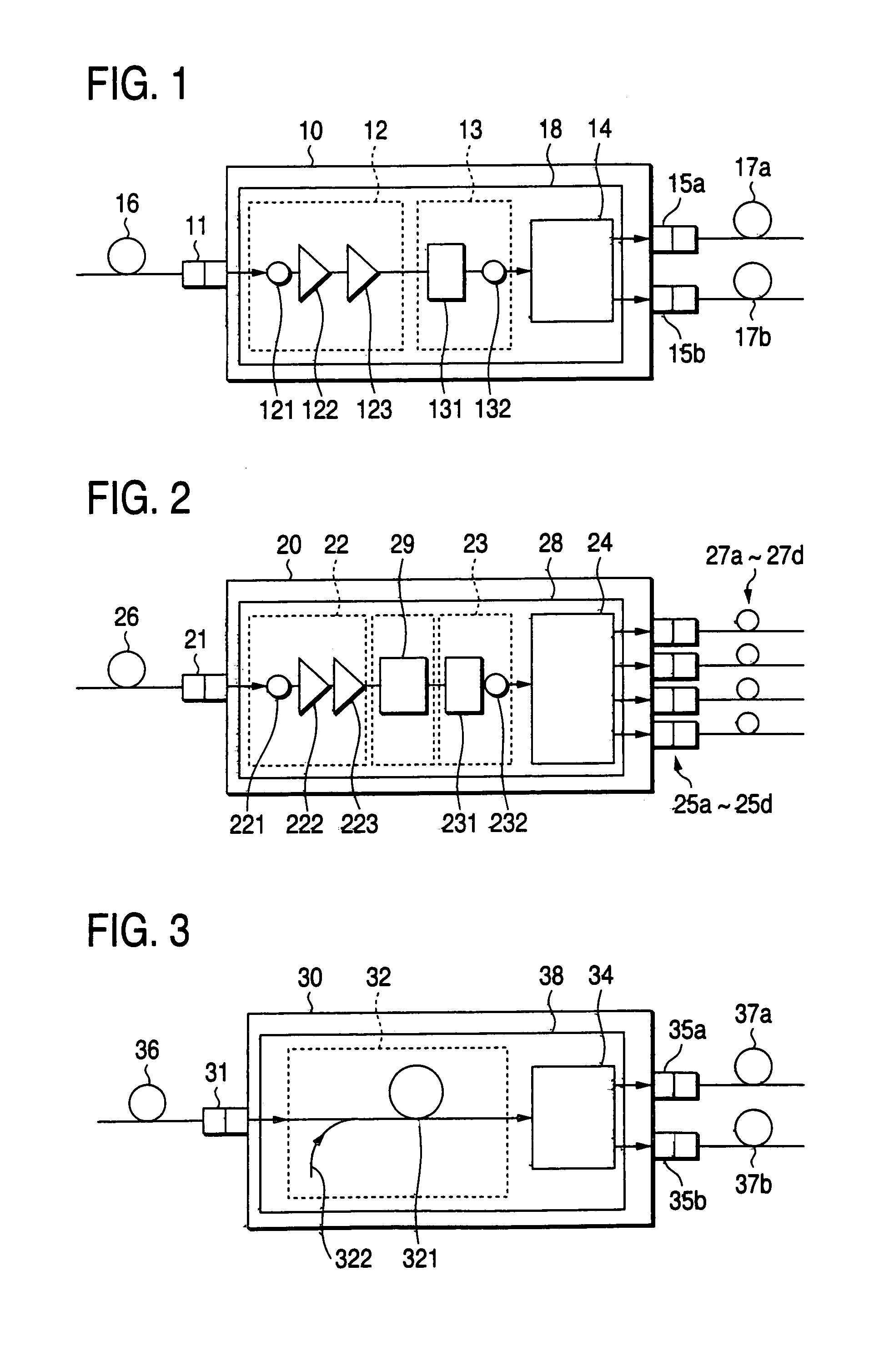
[0032]FIG. 1 is a diagram showing an optical distributor according to an embodiment of the invention. As shown in the figure, an optical distributor 10 includes an optical-signal input port 11, a light receiving device 12, a light emitting device 13, a light splitting device 14 and light-signal output ports 15a, 15b. The light receiving device 12 converts an optical light signal input to the optical-signal input port into an electric signal. The light emitting device 13 converts the electric signal into an optical signal. The optical splitter 14 splits the converted optical signal into two optical signals. The two optical-signal output ports 15a and 15b output the split two optical signals, respectively. The optical-signal input port 11 has a connector for connection to an optical fiber 16. The optical-signal output ports 15a and 15b have connectors for connection to optical fibers 17a an 17b, respectively. The light receiving device 12 includes a light receiving element 121 such as...


PUM


Abstract

An optical distributor includes an optical-signal input port, a light receiving device, a light emitting device, a light splitter, and optical signal output ports. The light receiving device converts an optical light signal input to the optical-signal input port into an electric signal. The light emitting device converts the electric signal into an optical signal. The optical splitter 14 splits the converted optical signal into two optical signals. The optical-signal output ports output the split optical signals. The light receiving device includes a light receiving element, a pre-amplifier, and a limiting amplifier. The light emitting device includes a light-source drive element and a light emitting element.

Description

[0001]The present disclosure relates to the subject matter contained in Japanese Patent Application No. 2002-292883 filed on Oct. 4, 2002, which is incorporated herein by reference in its entirety.BACKGROUND OF THE INVENTION[0002]1. Field of the Invention[0003]The present invention relates to an optical distributor for splitting an input optical signal and outputting the split optical signals, and an optical distributing system using the optical distributor.[0004]2. Description of the Related Art[0005]In an optical network system for transmitting an optical signal to a plurality of devices connected to optical fibers, optical splitters (optical distributors) each for splitting an optical signal and transmitting the split optical signals to the devices are disposed at respective positions. The optical signal is input to desired devices by way of the optical splitters. For the optical splitters of this type, the following optical splitters have been known.<Literature 1>[0006]F. ...

Claims


Application Information

Patent Timeline
IPC IPC(8): G02B6/26G02B6/28H04B10/27H04B10/272H04B10/29H04B10/299
CPCG02B6/2808H04B10/29G02B6/2817
Inventor YAMADA, HIDENORIOKADA, JUNJIUENO, OSAMUKYOZUKA, SHINYASATO, YOSHIHIDEKIJIMA, MASARU
Owner FUJIFILM BUSINESS INNOVATION CORP
Why Eureka
Try Eureka