Protective loading of stents

a protective sheath and stent technology, applied in the direction of prosthesis, forging/pressing/hammering apparatus, blood vessels, etc., can solve the problems of stent contact and potentially damaged, balloon pinching, and disturbing the coating

Active Publication Date: 2006-08-29
BOSTON SCI SCIMED INC
View PDF12 Cites 147 Cited by
  • Summary
  • Abstract
  • Description
  • Claims
  • Application Information

AI Technical Summary

Benefits of technology

[0014]The present invention is embodied in a variety of forms. In at least one embodiment the invention is directed to a crimpable and removable sheath or protector which may be placed onto the stent prior to the loading of the sent on to the catheter and / or crimping of the stent thereon. The protector eliminates direct contact between the loading and / or crimping apparatus and the stent. The stent used with the protector may be any type of implantable medical device. The stent may be a self-expanding, balloon expandable or hybrid stent.
[0016]In some embodiments the invention is directed to a contracting or crimping mould having one or more contracting apertures or openings which receive and / or draw the slack or folds of the protector which form as the stent is contracted and reduced in diameter. In some embodiments the contracting mould comprises one or more rods, each of which engage a fold of the protector to draw the folds away from the stent during contracting thereby ensuring that the points of contact between the protector and the stent remain free of folding or crinkling.

Problems solved by technology

It can also affect the dilatation length of the stent and lead to pinching of the balloon.
The manipulation of the catheter may cause the stent to be contacted and potentially damaged.
Where the stent includes or is coated with a drug or other material, such contact may disturb the coating and impair the proper delivery thereof.
In addition, contacting the stent during the loading and / or crimping process may result in the drug coating of the stent being contaminated with the residue of previous stent coatings that have been previously contacted by the loading and / or crimping system.

Method used


Image

  • Protective loading of stents
  • Protective loading of stents
  • Protective loading of stents

Examples


Embodiment Construction

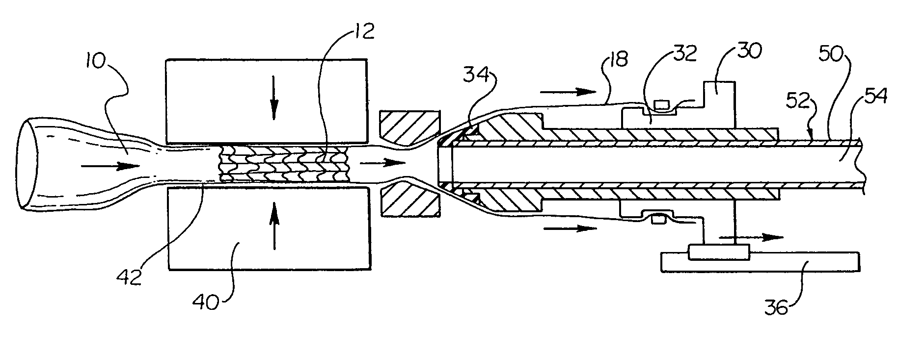
[0035]As may be seen in FIG. 1, in some embodiments the present invention is directed to a stent protector or sleeve 10 into which a stent 12 is positioned or placed. The protector is sized to readily accommodate passage of the stent 12 therein. The protector 10 has an inner diameter 14 that is greater than the outer diameter 16 of the stent 12 positioned therein, as a result the protector 10 is provided with a sufficient amount of diameter clearance to allow the stent to pass freely inside the protector 10.

[0036]The protector 10 comprises a substantially tubular wall 20 that defines a thickness of about 0.001 inches or thinner and may in some embodiments be in the range of 0.00025 inches or less.

[0037]The protector 10 may be constructed of a variety of material selected on the basis of bio-compatibility, tensile strength, impervious structure, and resistance to low temperature cracking if it becomes subject to crumpling or tight folding. Some examples of suitable material or materi...


PUM

PropertyMeasurementUnit
thicknessaaaaaaaaaa
thicknessaaaaaaaaaa
thicknessaaaaaaaaaa

Abstract

A system for protecting a stent from contact during loading comprises a stent, a protective sleeve disposed about the stent and a loading tool. The inner diameter of the protective sleeve is greater than the outer diameter of the stent. The protective sleeve has a length longer than that of the stent. The portion of the sleeve extending beyond the length of the stent defines a sleeve extension. The loading tool is positioned about at the stent retaining sleeve of a catheter. The tip region of the loading tool separates the protective sleeve and the stent from one another when the protective sleeve is pulled over the tip region of the loading tool. When the protective sleeve is pulled over the tip region of the loading tool the stent is advanced into a lumen defined by the stent retaining sleeve of the catheter.

Description

CROSS-REFERENCE TO RELATED APPLICATIONS[0001]Not ApplicableSTATEMENT REGARDING FEDERALLY SPONSORED RESEARCH[0002]Not ApplicableBACKGROUND OF THE INVENTION[0003]1. Field of the Invention[0004]The present invention relates generally to stents, stent loading stent contracting and stent delivery systems and their respective methods of use. Some embodiments of the invention are more specifically directed to a removable protective sheath which protects the stent from direct contact with a stent loading and / or stent contracting system. Some embodiments are more specifically directed to stent loading, contracting and / or delivery systems which are configured to accommodate such a protective sleeve and stent.[0005]2. Description of Related Art[0006]A stent is a generally tubular device that is used to support a bodily lumen. A stent is typically delivered to a desired bodily location via a catheter. Often the stent is loaded onto a portion of the catheter, such as a balloon or other region of...

Claims


Application Information

Patent Timeline
Patent Type & Authority Patents(United States)
IPC IPC(8): B23P19/04A61B17/00A61F2/06B21C9/00B21D41/00A61F2/84
CPCA61F2/95A61F2002/9522Y10T29/49865Y10T29/53987Y10T29/49927Y10T29/53996Y10T29/49925A61F2/9522A61F2/9524A61F2/9526
Inventor AUSTIN, MICHAELPERREAULT, DANIEL C.SOBRINO, GABRIEL S.
Owner BOSTON SCI SCIMED INC
Why Eureka
Try Eureka