Power tool

a technology of power tools and power tools, applied in the field of power tools, can solve the problems of increasing the weight of the entire hammer, affecting the appearance of the hammer, and complicated construction and assembly operations, so as to avoid complicating the construction of the power tool, improving the vibration reducing performance of the power tool

Active Publication Date: 2006-08-29
MAKITA CORP
View PDF9 Cites 51 Cited by
  • Summary
  • Abstract
  • Description
  • Claims
  • Application Information

AI Technical Summary

Benefits of technology

[0006]Accordingly, it is an object of the present invention to provide a technique for further improving the vibration reducing performance in the power tool, while avoiding complicating the construction of the power tool.
[0007]According to the present invention, a representative power tool may comprise a striker, a tool bit and a vibration reducer. The striker reciprocates by pressure fluctuations within a cylinder. The tool bit performs a predetermined operation by a striking force of the striker. The vibration reducer serves to reduce vibration on the striker by reciprocating in a direction opposite to the reciprocating direction of the striker. The path of the center of gravity of the vibration reducer is arranged to coincide with a path of the center of gravity of the striker. With such construction, the vibration reducer can be closely associated with the striker without requiring any vibration-isolating chamber, it can be avoided to complicate the construction of the power tool with a vibration reducing function. Further, because the paths of the center of gravity of the striker and the vibration reducer coincide to each other and thus rotating (turning) moment is not exerted onto the reciprocating cylinder during the operation of the power tool, vibration reduction can be performed in a stable manner.

Problems solved by technology

Therefore, the construction and assembling operation are complicated and the weight of the entire hammer is increased.
Further, because the space for housing the dynamic vibration reducer must be ensured, the appearance of the hammer is impaired.

Method used


Image

  • Power tool
  • Power tool
  • Power tool

Examples


first representative embodiment

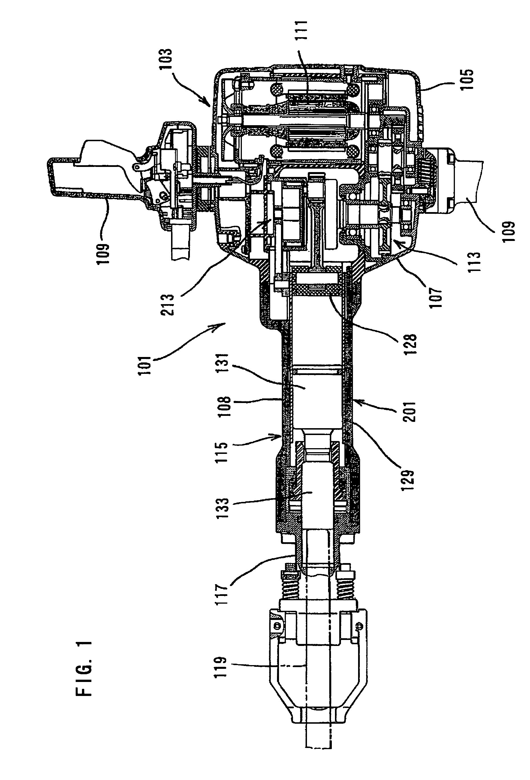
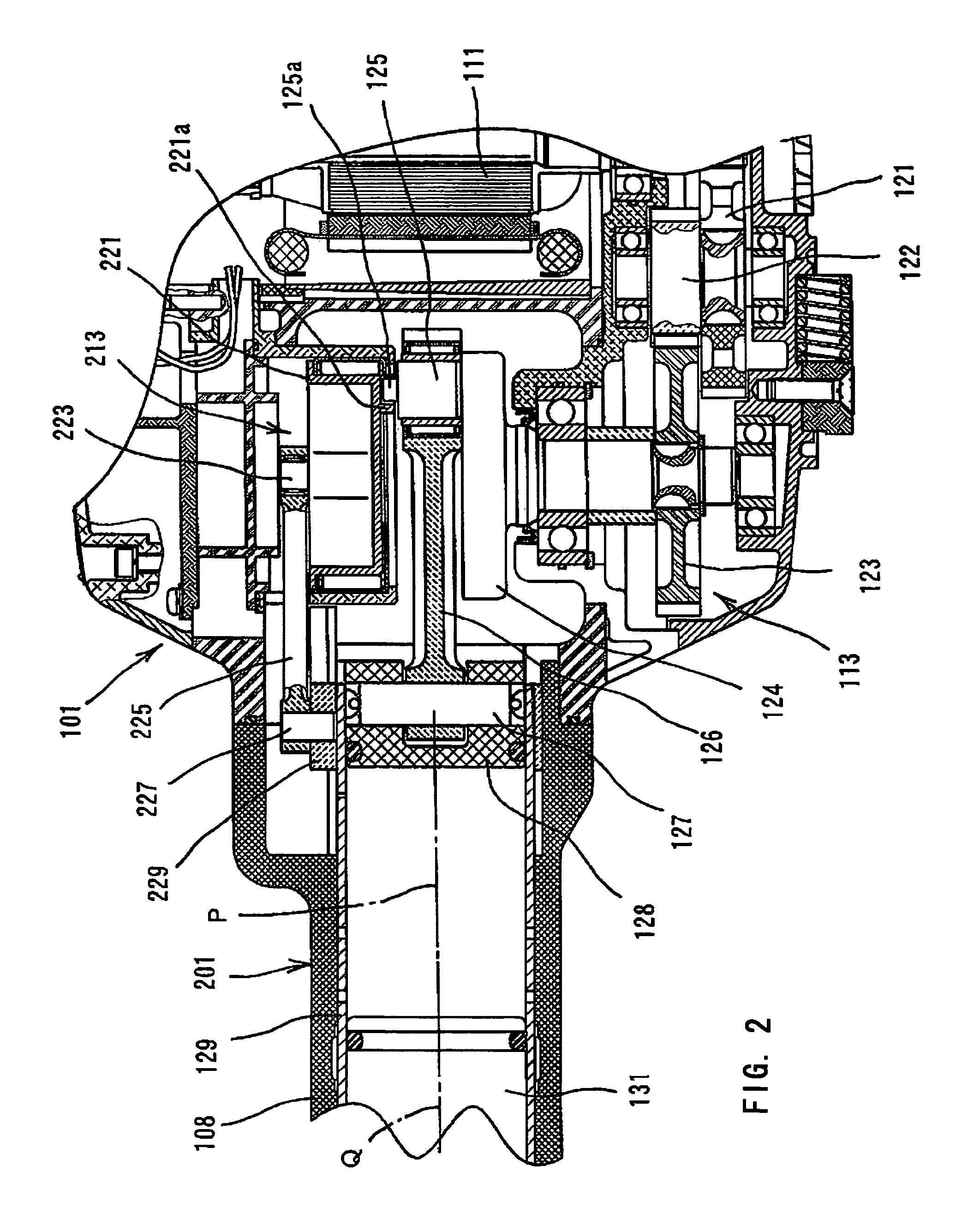
[0024]First representative embodiment of the present invention will now be described with reference to the drawings. As shown in FIG. 1, an electric hammer 101 as a representative embodiment of the power tool according to the present invention comprises a body 103, a tool holder 117 connected to the tip end region of the body 103, and a hammer bit 119 detachably coupled to the tool holder 117. The hammer bit 119 is a feature that corresponds to the “tool bit” according to the present invention. FIG. 2 shows the electric hammer 101 in plan view.

[0025]The body 103 includes a motor housing 105, a gear housing 107 and a handgrip 109. The motor housing 105 houses a driving motor 111. The gear housing 107 houses a first motion converting mechanism 113, a second motion converting mechanism 213 and a striking mechanism 115. The first motion converting mechanism 113 is adapted to convert the rotating output of the driving motor 111 to linear motion and then to transmit it to the striking mec...

second representative embodiment

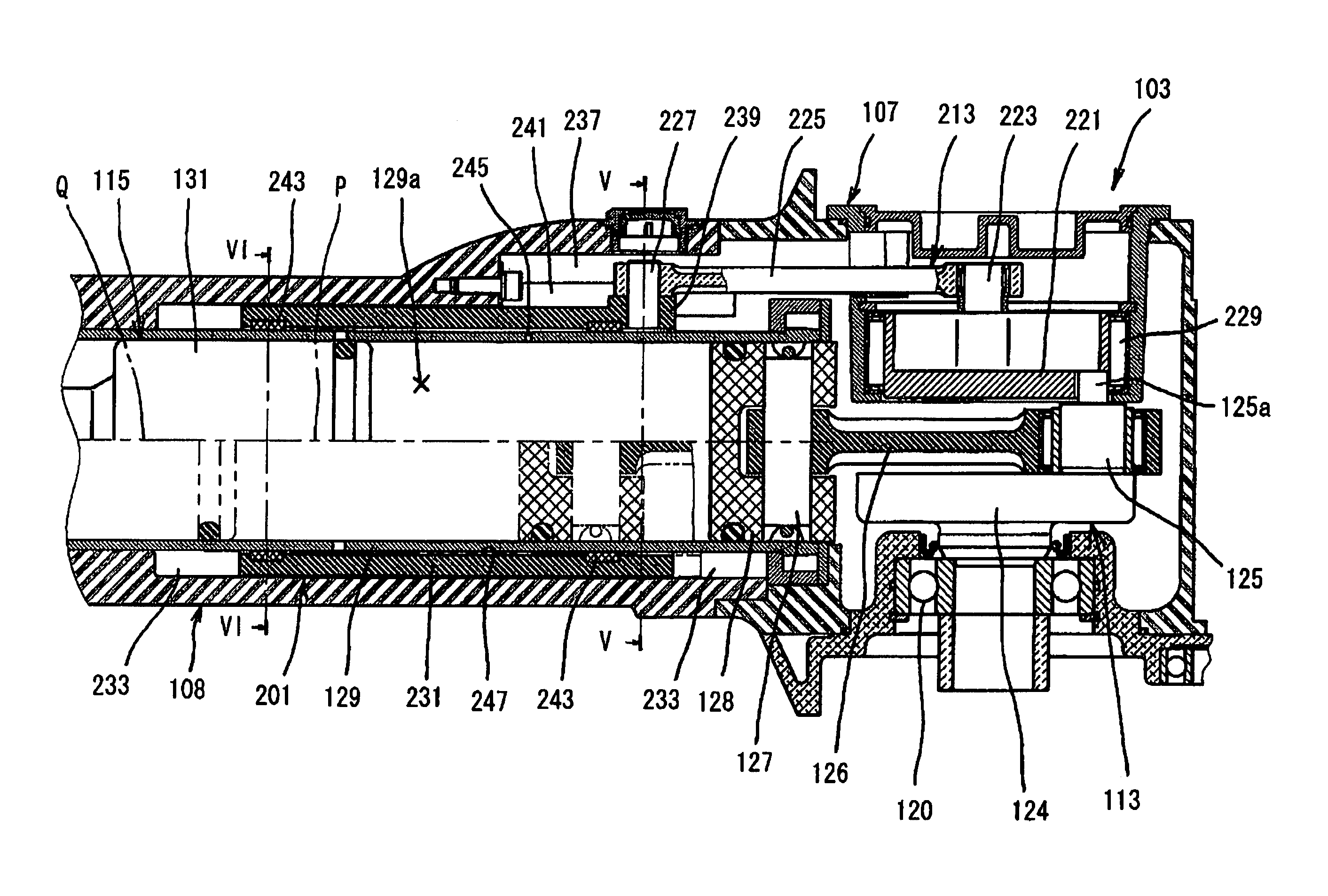
[0043]Second representative embodiment of the present invention is now explained in greater detail in reference to FIGS. 4 to 8. In explaining the second embodiment, features having substantially the same constructions with the respective features utilized in the above-explained first embodiment are shown with same reference numbers in the drawings. As shown in FIGS. 4 and 5, the cylinder 129 of the second representative embodiment is fixedly disposed within the barrel 108 that is connected to the gear housing 107. Further, a cylindrical counter weight 231 is disposed between the outer circumferential surface of the cylinder 129 and the inner circumferential surface of the barrel 108. The cylindrical counter weight 231 can slide in the axial direction of the hammer bit 119 so as to function as a vibration reducing weight during hammering operation by reciprocating in a direction opposite to the sliding direction of the striker 131. A cylindrical accommodation space 233 for accommoda...


PUM

PropertyMeasurementUnit
crank angleaaaaaaaaaa

Abstract

It is an object of the invention to provide a technique for further improving the vibration reducing performance in the power tool, while avoiding complicating the construction of the power tool. According to the present invention, a representative power tool may comprise a striker, a tool bit and a vibration reducer. The vibration reducer serves to reduce vibration on the striker by reciprocating in a direction opposite to the reciprocating direction of the striker. The path of the center of gravity of the vibration reducer is arranged to coincide with a path of the center of gravity of the striker. With such construction, because rotating moment is not exerted onto the reciprocating cylinder during the operation of the power tool, vibration reduction can be performed in a stable manner.

Description

BACKGROUND OF THE INVENTION[0001]1. Field of the Invention[0002]The present invention relates to a power tool, and more particularly, to a technique of reducing and alleviating vibration in a power tool, such as a hammer and a hammer drill.[0003]2. Description of the Related Art[0004]Japanese non-examined laid-open Patent Publication No. 52-109673 discloses a hammer with a vibration reducing device. The known hammer includes a vibration-isolating chamber provided in the region under the body housing of the hammer. A dynamic vibration reducer is housed in the vibration-isolating chamber and serves to reduce and alleviate strong vibration developed in the axial direction of the hammer during the operation.[0005]However, the vibration-isolating chamber is separately formed within the body housing and components parts of the dynamic vibration reducer are incorporated therein. Therefore, the construction and assembling operation are complicated and the weight of the entire hammer is incr...

Claims


Application Information

Patent Timeline
Patent Type & Authority Patents(United States)
IPC IPC(8): B25D11/00B25D11/12B25D17/24
CPCB25D11/125B25D17/24B25D2217/0088
Inventor IKUTA, HIROKIARAKAWA, TAKUOKAWAKAMI, TAKAHIRO
Owner MAKITA CORP
Why Eureka
Try Eureka