Anodic protection of electrical contacts

anode corrosion and anode corrosion technology, applied in the direction of deaf-aid sets, coupling device connections, electrical apparatus, etc., can solve the problems of voltage-induced erosion, neither method, however, provides adequate protection from voltage-induced erosion, and achieves the effect of reducing the incidence of anode corrosion and preventing galvanic anode corrosion

Active Publication Date: 2006-08-29
ADVANCED BIONICS AG
View PDF3 Cites 22 Cited by
  • Summary
  • Abstract
  • Description
  • Claims
  • Application Information

AI Technical Summary

Benefits of technology

[0015]In another aspect of the invention, a method of preventing galvanic anode corrosion is disclosed, the method comprising: providing a sacrificial anode having a positive voltage potential and strategically positioning the sacrificial anode to distort the electrical field between the negative and positive contacts to thereby reduce the incidence of anode corrosion.
[0016]It is a feature of the present invention that when a sacrificial anode is placed on a discardable compone

Problems solved by technology

Yet, over time, this parallel, parasitic flow of current can result in voltage-induced erosion, from corrosion of the positive contact (anod

Method used


Image

  • Anodic protection of electrical contacts
  • Anodic protection of electrical contacts
  • Anodic protection of electrical contacts

Examples


Embodiment Construction

[0029]The following description is of the best mode presently contemplated for carrying out the invention. This description is not to be taken in a limiting sense, but is made merely for the purpose of describing the general principles of the invention. The scope of the invention should be determined with reference to the claims.

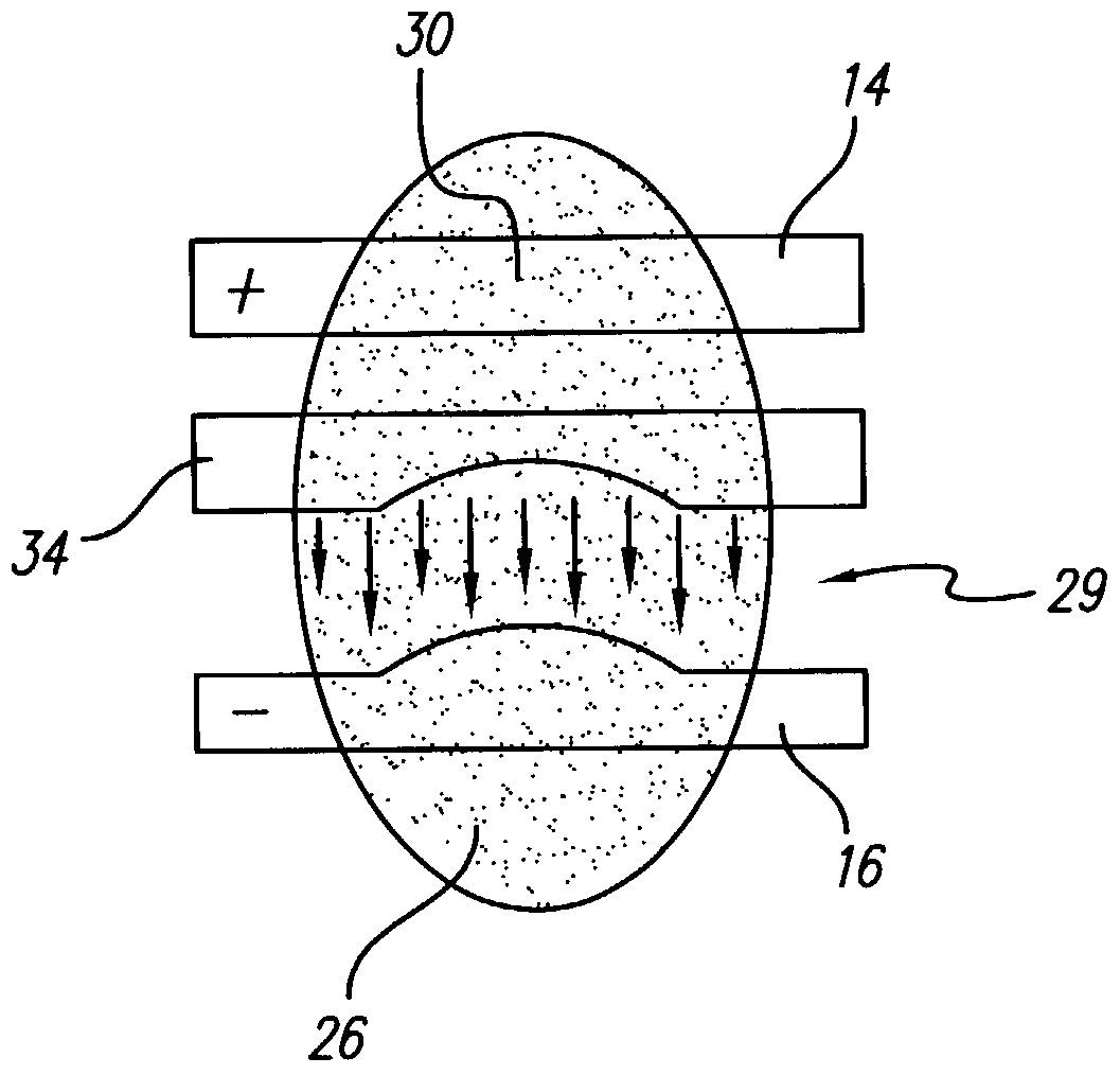
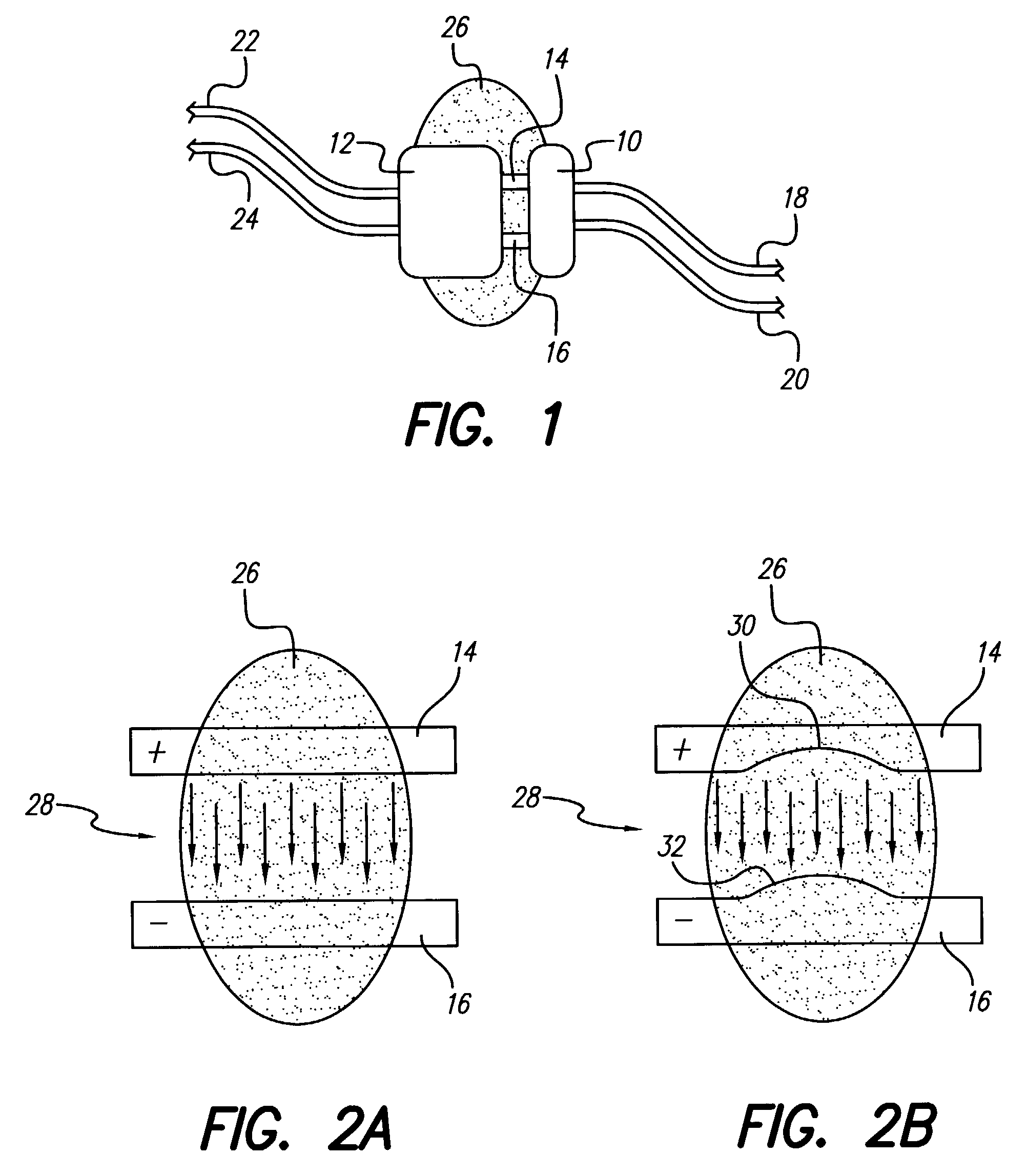
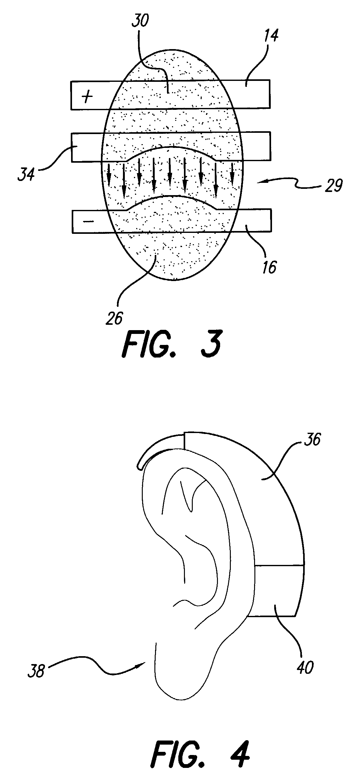
[0030]The present invention may be applied to any instance where a component or device has positive and negative contacts or connectors that are used to connect to another component or device and the contacts become immersed in a conductive solution that forms a parallel electrical circuit or shunt. Over time, the anode contact may become eroded, which can mechanically weaken the connection, and in some cases lead to a complete break in the connection. The present invention provides a device and method for protecting the anode.

[0031]The device of the present invention is a sacrificial anode that is configured and strategically placed in proximity to the posi...


PUM


Abstract

An anode protection device and method are provided. The method includes placing a sacrificial anode in proximity to the positive and negative contacts to shield or distort the field therebetween which provides preferential corrosion of the sacrificial anode, instead of the anode. The protection device is a sacrificial anode having various forms and placed in different configurations. In one form the sacrificial anode is a plate. In another form the sacrificial anode is a ring placed around either the positive contact or negative contact to provide a shield between the negative and positive contacts. In a further device embodiment, the sacrificial anodic plate can be welded to the aluminum case of a rechargeable battery of a behind-the-ear (BTE) hearing device.

Description

BACKGROUND OF THE INVENTION[0001]The present invention relates to methods and devices for preventing or reducing a voltage-induced corrosion of a positive (anodic) contact. In particular the invention is related to anodic protection when both positive and negative contacts are immersed in a conductive solution.[0002]Electrical devices often have positive and negative contacts or connectors to enable one device or component to be electrically connected to another device or component. When the negative and positive contacts are immersed in a conductive fluid, such as perspiration, a parallel circuit can be created between the negative and positive contacts which, over time, can cause anodic material to corrode and dissolve into the conductive solution and form a deposit over the negative (cathodic) contact.[0003]One such instance where anodic corrosion can occur is with multi-component hearing devices, such as a behind-the-ear (BTE) hearing aid or a BTE component of a cochlear implant...

Claims


Application Information

Patent Timeline
IPC IPC(8): C23F13/00H01R9/05H01R13/646
CPCH01R9/0518H01R2103/00
Inventor TZIVISKOS, GEORGEFERNALD, C. GEOFFREY E
Owner ADVANCED BIONICS AG
Why Eureka
Try Eureka