Temporary cellular antenna site

a cellular antenna and site technology, applied in the direction of resonant antennas, elongated active elements, industrial buildings, etc., can solve the problems of delayed erection of antennas and ultimately the operation of cellular sites, towers or monopoles that are not readily removed and redeployed, and cost and time-consuming

Inactive Publication Date: 2006-08-29
CREATIVE DESIGN
View PDF9 Cites 12 Cited by
  • Summary
  • Abstract
  • Description
  • Claims
  • Application Information

AI Technical Summary

Benefits of technology

[0012]The base of the cellular antenna site of the present invention provides integral means for securing an electrical cabinet which houses the required telecommunications electronics, as well as means for mounting any other auxiliary enclosures, cabinets, or shelters. The base also includes integral means for mounting the hinged antenna base, so that the antenna may be first attached in a horizontal position and then erected by simply hoisting it into a vertical position about a hinge, avoiding any need for a crane. Once erected, the hinged antenna base can be secured to maintain the antenna in the vertical position. A simple weatherproof wiring harness electrica

Problems solved by technology

Therefore, these structures often require special zoning and permitting, soil core sampling, engineering, excavation, and the use of heavy equipment and cranes to perform installation, all of which may be costly and time consuming.
In addition, the time required to pour and cure a concrete foundation may delay the erection of an antenna and ultimately the operation of the cellular site.
Further, such a permanent tower or monopole is not readily removed and re

Method used


Image

  • Temporary cellular antenna site
  • Temporary cellular antenna site
  • Temporary cellular antenna site

Examples


Embodiment Construction

[0025]The following detailed description is of the best presently contemplated mode of carrying out the invention. The description is not intended in a limiting sense, and is made solely for the purpose of illustrating the general principles of the invention. The various features and advantages of the present invention may be more readily understood with reference to the following detailed description taken in conjunction with the accompanying drawings.

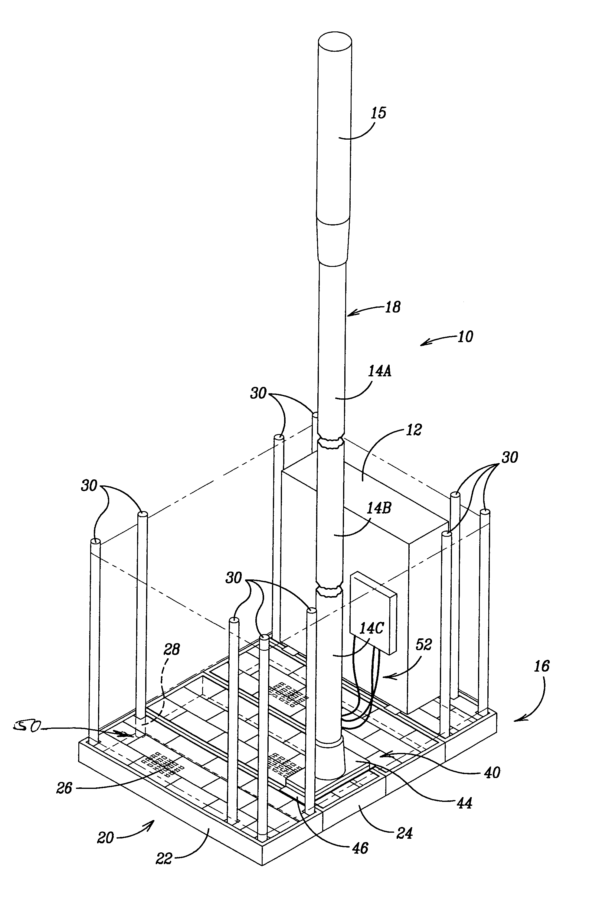
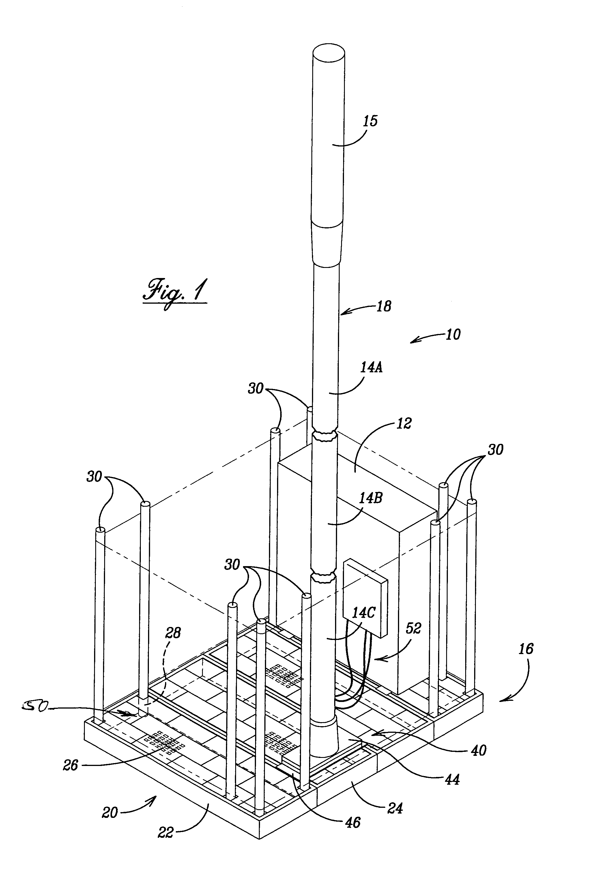
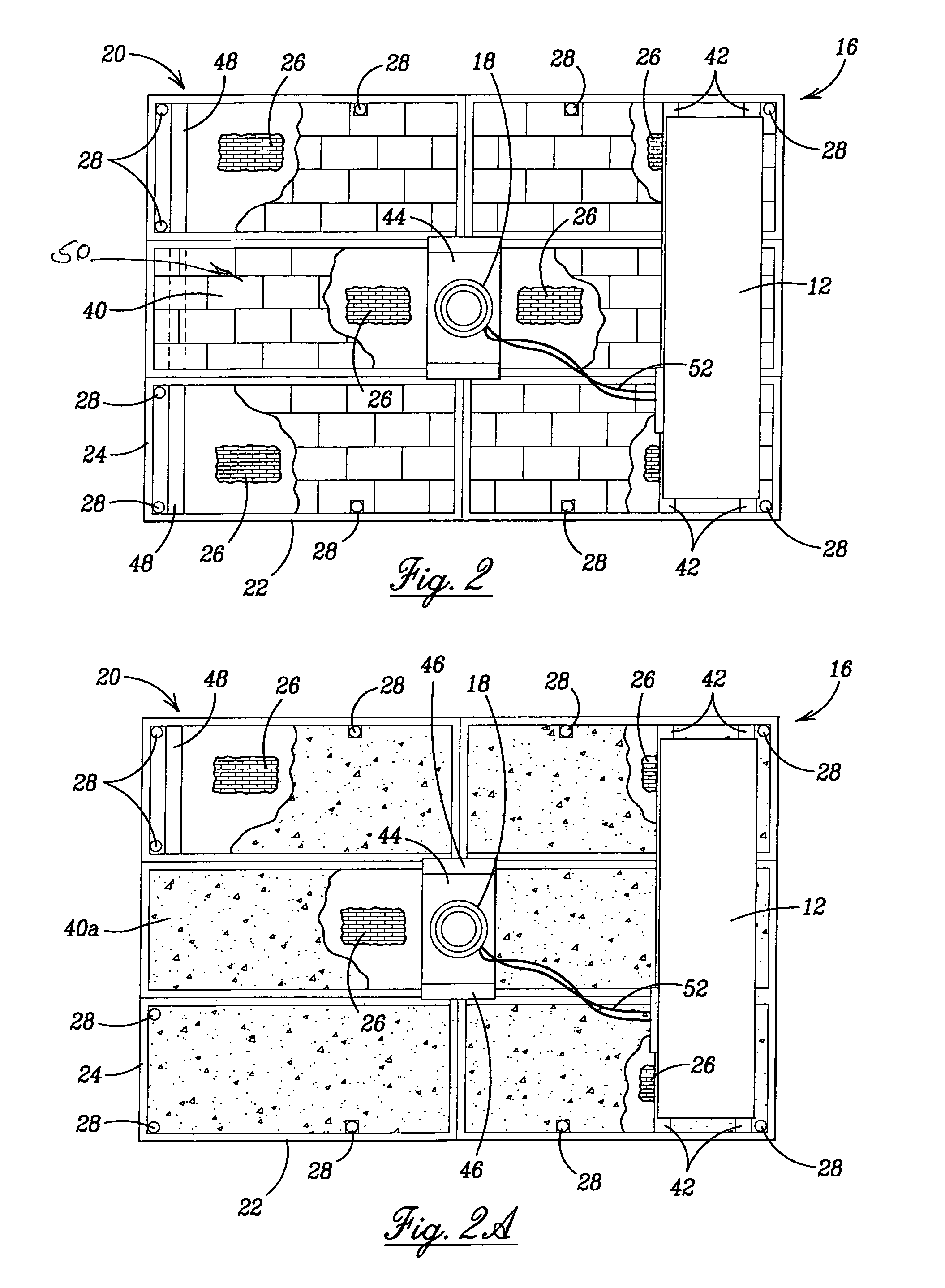
[0026]Referring now to the drawings in detail, where like numerals refer to like parts or elements, there is shown in FIG. 1 a perspective view of the temporary cellular antenna site apparatus 10. The apparatus 10 is of modular construction comprising a base 16, an antenna system 18, an electrical cabinet 12, fencing 38, and a grounding means (not shown). An additional component required for the functioning of the apparatus 10 is anchoring ballast, which may be in the form of concrete blocks 40, poured concrete 40a, crushed gravel 40b...


PUM


Abstract

A small-footprint portable modular cellular antenna site capable of being deployed on any substantially level, flat piece of ground, the cellular antenna site being easily assembled, disassembled, and moved without the aid of heavy equipment. The cellular antenna site does not require a permanent foundation, but instead is anchored by weighting with a non-damaging ballast material sufficient to support a small diameter 30 to 60 foot high antenna pole at wind speed ratings up to 100 miles per hour. The cellular antenna site includes a modular base configurable in different geometric arrangements that retains the ballast material and supports a segmented monopole antenna, an electrical cabinet, perimeter fencing with an access gate, and any auxiliary cabinets, enclosure, or shelters as may be required.

Description

BACKGROUND OF THE INVENTION[0001]The present invention relates generally to devices for cellular telephone transmission equipment and more particularly to a self-contained cellular antenna site adapted to be small in footprint, quickly assembled without the use of heavy equipment, and easily disassembled for transporting.[0002]The continued proliferation and widespread use of wireless telecommunications equipment has brought with it the need for more self-contained cellular antenna sites. Typical methods of deploying cellular antennas are on permanent structures such as towers or monopoles, or on rooftops. When based on the ground, the permanent structures are normally supported on conventional foundations such as reinforced concrete slabs or pads, and often the concentrated weight of a tall antenna tower has required a relatively substantial and separate foundation member such as a deep reinforced concrete pier. Therefore, these structures often require special zoning and permittin...

Claims


Application Information

Patent Timeline
IPC IPC(8): H01Q1/12E04H5/02E04H12/22H01Q1/24H01Q9/34
CPCE04H5/02H01Q9/34H01Q1/246E04H12/2238
Inventor RYAN, RALPH E.
Owner CREATIVE DESIGN
Why Eureka
Try Eureka