Optical fiber cable

a technology of optical fiber and amplifier, applied in the direction of optical elements, electromagnetic repeaters, instruments, etc., can solve the problems of wavelength dispersion, transmission loss, deterioration of wdm optical signal waveform,

Inactive Publication Date: 2006-08-29
FUJITSU LTD
View PDF28 Cites 14 Cited by
  • Summary
  • Abstract
  • Description
  • Claims
  • Application Information

AI Technical Summary

Benefits of technology

[0035]In addition, objects of the present invention are achieved by providing an apparatus including a transmission line and a pump light source. The transmission line includes first, second and third optical fibers connected together from an input end to an output end of the transmission line so that a signal light travels through the input end, then through the first optical fiber, then through the second optical fiber, then through the third optical fiber and then through the output end. The first, second and third optical fibers have first, second and third characteristic values, respectively. The second characteristic value is larger than the first characteristic value and the third characteristic value. The characteristic value of a respective optical fiber being a nonlinear refractive index of the optical fiber divided by an effective cross section of the optical fiber. The pump light source supplies pump light to the transmission line so that the signal light is amplified by Raman amplification as the signal light travels through the transmission line

Problems solved by technology

While being transmitted through the optical transmission line, the WDM optical signal deteriorates in its waveform due to wavelength dispersion, transmission loss, and a nonlinear optical effect.
In realizing long distance transmission of an optical signal with less error ratio, there is a problem that the wavelength dispersion, the transmission loss, and the nonlinear optical effect need to be compensated in a well-balanced manner as a whole instead of compensating only one physical quantity.

Method used


Image

  • Optical fiber cable
  • Optical fiber cable
  • Optical fiber cable

Examples


Embodiment Construction

[0063]Reference will now be made in detail to the present preferred embodiments of the present invention, examples of which are illustrated in the accompanying drawings, wherein like reference numerals refer to like elements throughout.

[0064]FIG. 3 is a diagram showing the structure of an optical communication system, according to an embodiment of the present invention.

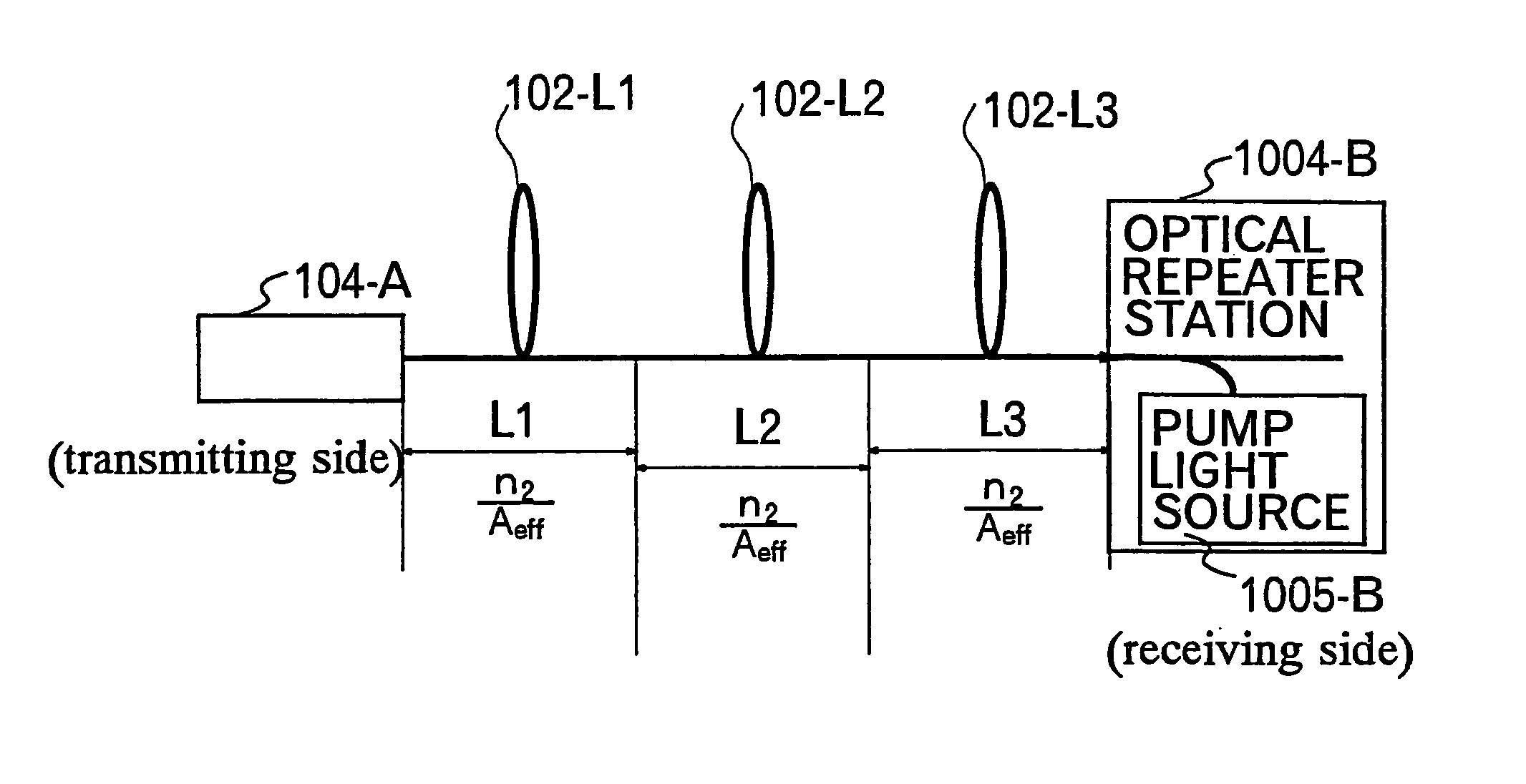
[0065]FIGS. 4A, 4B and 4C are diagrams showing the structure of a totally managed / distributed Raman amplifier and charts showing optical signal power and accumulated wavelength dispersion, and showing a partial structure between two stations in the optical communication system.

[0066]Referring now to FIG. 3 and FIGS. 4A, 4B and 4C, the optical communication system includes an optical transmitting station 101 generating a WDM optical signal including a plurality (for example, “m”) optical signals at different wavelengths multiplexed together. The generated WDM optical signal is transmitted through an optical transmissio...


PUM

PropertyMeasurementUnit
wavelength dispersionaaaaaaaaaa
wavelengthsaaaaaaaaaa
transmission distanceaaaaaaaaaa

Abstract

An optical fiber cable including a plurality of optical fibers, each optical fiber having a characteristic value in a middle field which is larger than characteristic values in fields other than the middle field of the optical fiber. The characteristic value in a respective field is a nonlinear refractive index of the optical fiber in the field divided by an effective cross section of the optical fiber in the field. The middle field and the characteristic value in the middle field are set as a combination to suppress a nonlinear phase shift generated in light transmitted through the plurality of optical fibers.

Description

CROSS-REFERENCE TO RELATED APPLICATIONS[0001]This application is a divisional of application Ser. No. 10 / 755,384, filed Jan. 13, 2004, now U.S. Pat. No. 6,934,454 which is a divisional of application Ser. No. 09 / 984,489, filed Oct. 30, 2001, now U.S. Pat. No. 6,721,481, issued Apr. 13, 2004.[0002]This application claims priority to Japanese application No. 2000-330966, filed Oct. 30, 2000, and which is incorporated herein by reference.BACKGROUND OF THE INVENTION[0003]1. Field of the Invention[0004]The present invention relates to a distributed optical amplifying apparatus which can serve both as an optical transmission line and an optical amplifying medium, and more particularly, to a distributed optical amplifying apparatus which can compensate transmission loss, prevent a nonlinear optical effect, and improve an optical signal-to-noise ratio. Moreover, the present invention relates to an optical fiber cable suitable for the distributed optical amplifying apparatus, an optical comm...

Claims


Application Information

Patent Timeline
Patent Type & Authority Patents(United States)
IPC IPC(8): G02B6/44G02F1/35H01S3/06H01S3/067H01S3/10H01S3/30H04B10/077H04B10/079H04B10/2507H04B10/2519H04B10/2525H04B10/2537H04B10/29H04B10/294H04B10/297
CPCH04B10/25253H04B10/2916G02B6/29377G02B6/02252G02B6/02266G02B6/262H04B2210/003H01S3/302
Inventor TERAHARA, TAKAFUMIHAINBERGER, RAINERHOSHIDA, TAKESHI
Owner FUJITSU LTD
Why Eureka
Try Eureka