Heat dissipation device having heat pipe

a heat dissipation device and heat pipe technology, which is applied in indirect heat exchangers, lighting and heating apparatus, and semiconductor/solid-state device details, etc., can solve the problems of insufficient heat dissipation from the cpu, heat dissipation devices, and inability to optimally utilize heat pipes, so as to achieve efficient heat removal from the heat generating device, evenly distribute heat, and reduce the effect of fin width

Inactive Publication Date: 2006-09-05
HON HAI PRECISION IND CO LTD
View PDF12 Cites 55 Cited by
  • Summary
  • Abstract
  • Description
  • Claims
  • Application Information

AI Technical Summary

Benefits of technology

[0007]Accordingly, what is needed is a heat dissipation device accompanying phase change, which is able to efficiently remove heat from a heat

Problems solved by technology

The conventional heat sink, which is made of a simple slotted metal block attached on the CPU, is no longer a satisfactory means for dissipating heat from the CPU.
However, the conventional heat dissipation device with heat pipe has the following disadvantage.
First, the heat pipes cannot optimally utilized either when they are extended parallel to each other or when they are extended in a nonparallel manner.
The increase of the width of the fins is quite disadvantag

Method used


Image

  • Heat dissipation device having heat pipe
  • Heat dissipation device having heat pipe
  • Heat dissipation device having heat pipe

Examples


Embodiment Construction

[0014]Reference will now be made to the drawing figures to describe the present invention in detail.

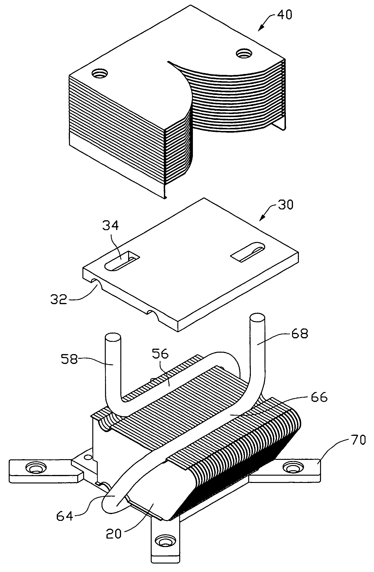
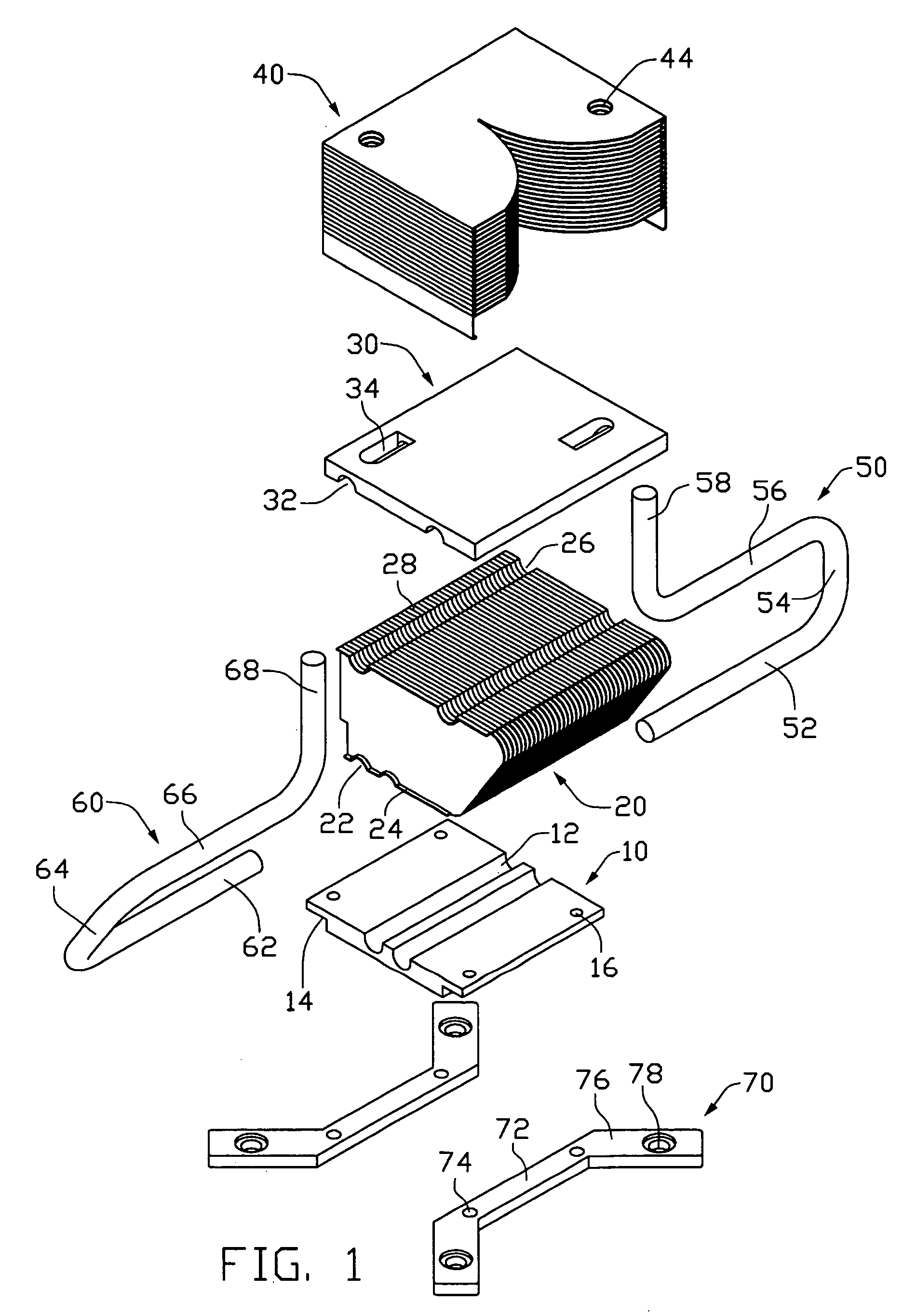
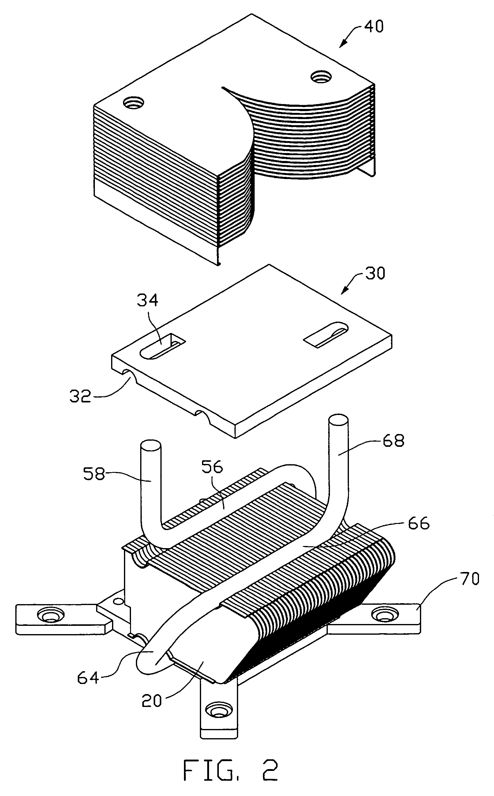
[0015]Referring to FIG. 1, a heat dissipation device of the preferred embodiment of the present invention is used for mounting to a printed circuit board (not shown) to remove heat from a heat-generating electronic device (not shown) mounted to the printed circuit board, such as a CPU. The heat dissipation device comprises a base 10, a plurality of vertical fins 20 attached to the base 10, a plate 30 on the vertical fins 20, a plurality of horizontal fins 40 on the plate 30 and first and second heat pipes 50, 60. The heat dissipation device further comprises two locking members 70 engaging with the base 10 to secure the heat dissipation device to the printed circuit board.

[0016]The base 10 is a metal plate having a high heat conductivity, and has a rectangular configuration. The base 10 comprises a bottom surface (not labeled) for contacting with the electronic device and a top surfac...


PUM


Abstract

A heat dissipation device includes a base, a plurality of first fins, a plate, a plurality of second fins and two heat pipes. Each heat pipe includes a heat-receiving portion sandwiched between the base and the first fins, a heat-exchange portion sandwiched between the plate and the first fins, a connecting portion connecting the heat-receiving portion and the heat-exchange portion, a heat-discharging portion extending through the plate and inserted into the second fins. At least one of the heat pipes defines two different planes which intercross at the heat-exchange portion of the at least one of the heat pipes.

Description

BACKGROUND[0001]1. Field[0002]The present invention relates generally to a heat dissipation device, and more particularly to a heat dissipation device for cooling a heat-generating electronic device, having uniquely configured heat pipes to enhance heat dissipation capability thereof.[0003]2. Description of Related Art[0004]It is widely acknowledged that heat is produced during operation of electronic devices such as central processing units (CPUs). The heat produced must be quickly removed to ensure the CPUs to work normally. Typically, a heat sink is provided to remove heat from the CPU. More and more electronic components are integrated on the CPU, which makes the CPU hotter and hotter during operation. The conventional heat sink, which is made of a simple slotted metal block attached on the CPU, is no longer a satisfactory means for dissipating heat from the CPU.[0005]Phase change equipments, such as heat pipes are developed to assist heat management of the heat-generating elect...

Claims


Application Information

Patent Timeline
IPC IPC(8): F28D15/00H05K7/20
CPCF28D15/0266F28F1/32H01L23/427F28D15/0275H01L2924/0002F28F2215/12H01L2924/00
Inventor WU, YI-QIANGDENG, WEIZHAO, LIANG-HUIDENG, GEN-PING
Owner HON HAI PRECISION IND CO LTD
Why Eureka
Try Eureka