Rotatable coin display

a coin display and rotating technology, applied in the field of mounting and displaying coins, can solve the problems of compounding the problem of maintaining rotational alignment, customer dissatisfaction, and flange damage, and achieve the effects of preventing flange damage, facilitating bubble rotation, and preventing undesirable “humps”

Active Publication Date: 2006-09-05
PFYLUM LLC
View PDF18 Cites 12 Cited by
  • Summary
  • Abstract
  • Description
  • Claims
  • Application Information

AI Technical Summary

Benefits of technology

[0008]The display can also include an apparatus for rotatably securing the flange of the bubble between the first and second support layers so that the bubble may be rotated relative to the first and second layers of support material. This can comprise, for example, a layer of a smooth, heat-resistant coating, such as a high-gloss UV coating, applied to a portion of the back surface of either the first or second support layer, or to both layers. Generally, the smooth heat-resistant coating is applied to the support layer(s) over the region in which the layer(s) contact the flange of the bubble. The apparatus helps prevent the flange from adhering to the support layers, and facilitates the rotation of the bubble within the display.
[0009]According to another aspect, the display can also include a third support layer b...

Problems solved by technology

Proper rotational alignment of the coin within the surrounding packaging of the display is an important consideration for many customers, and even a minuscule rotation of the coin within the display can cause consumer dissatisfaction.
Also, because the “ideal” coin alignment is a matter of personal preference, customers are sometimes dissatisfied even when the coins are properly aligned in the display.
The problem of maintaining rotational alignment is compounded when multiple coins are provided in a single display.
This rotational alignment problem results in a significant increase in manufacturing costs in order to assure consistent quality for the displays.
This approach does suffer from some drawbacks.
The adhesive used to join the cards together tends to adhere to the flange, which can make rotation of the coin in the display extremely difficult, if not imposs...

Method used


Image

  • Rotatable coin display
  • Rotatable coin display
  • Rotatable coin display

Examples


Embodiment Construction

[0020]A description of preferred embodiments of the invention follows.

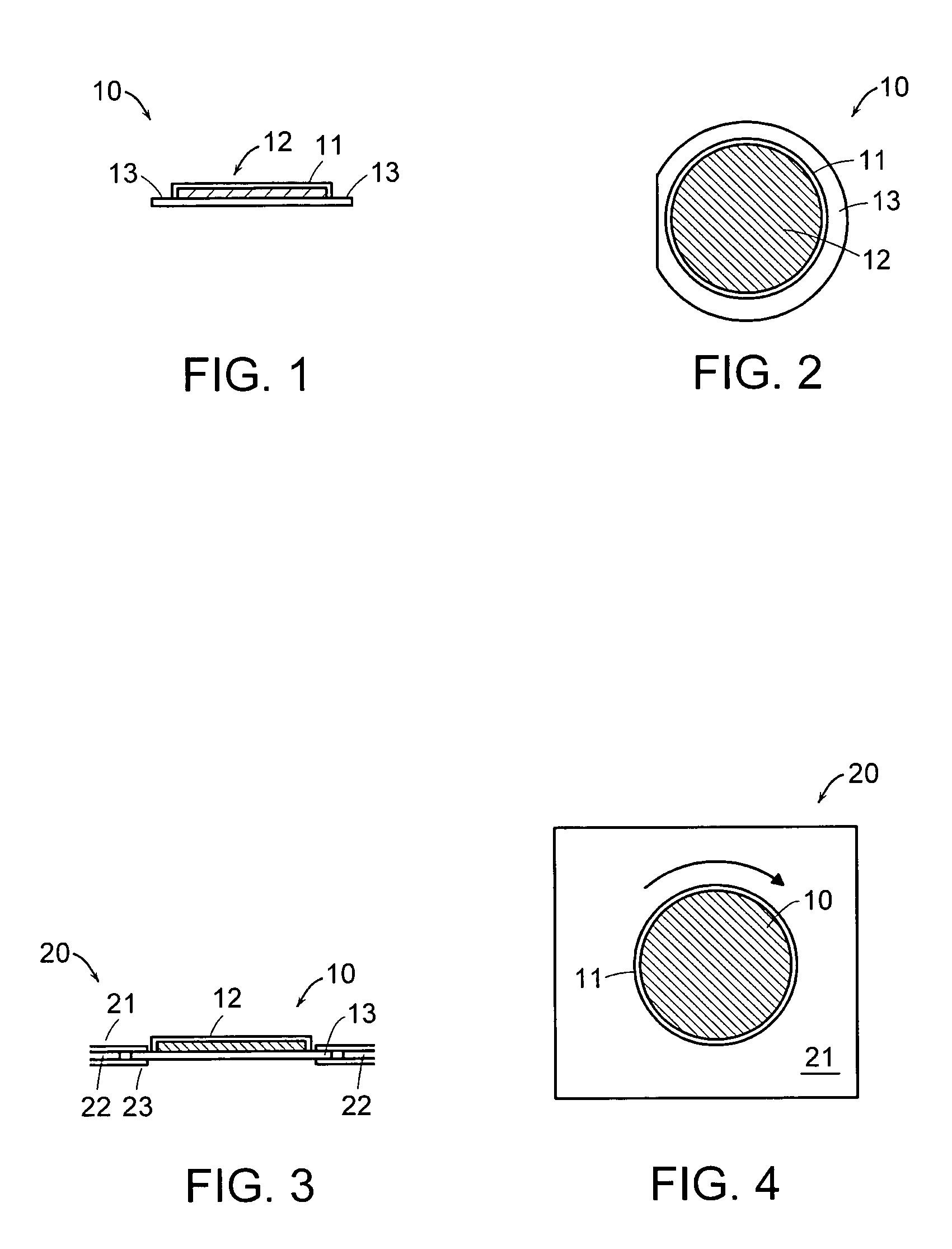
[0021]FIG. 1 is a side view of a coin 11 encapsulated within a bubble 10. The bubble is preferably comprised of a semi-rigid transparent material, such as a plastic, that is vacuum-formed to the size and shape of the coin. As shown in FIG. 2, the bubble 10 includes a central capsule 12 containing the coin 11, where the shape of the capsule is roughly commensurate with the shape of the coin. The bubble also includes a flange 13 which extends from the outer perimeter of the capsule 12.

[0022]The bubble can comprise two separate pieces that are joined together to encapsulate the coin. In other embodiments, the bubble can comprise a single piece that is folded over to form a central capsule and the flange.

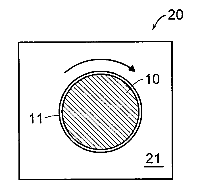
[0023]FIG. 3 is a cross-section of a laminated assembly 20 with a rotatable coin bubble 10. The laminated assembly includes three layers of a rigid or semi-rigid material, such as card stock, which support the bubble ...


PUM


Abstract

A display for a collectible item, such as a coin, in which the collectible item may be rotated relative to the display. In one embodiment, the display comprises a bubble, which can be a semi-rigid transparent material, supported between at least two layers of support material, which can be a rigid material such as card-stock, which are adhered together. The bubble includes a capsule for encapsulating the collectible item, and a flange extending from an outer perimeter of the capsule. The capsule of the bubble is aligned within an opening in the support material so that the collectible item may be viewed. The flange contacts the support layers, and permits the bubble to be rotated within the display. The display also includes an apparatus for rotatably securing the flange between the support layers, which can be a high-gloss heat-resistant coating applied to the support layers over the areas in which the support layers contact the flange. The display can also include a third support layer between the first and second layers. The third layer has an opening that is slightly larger than the flange, so that the flange is located within the opening. The third layer preferably has a thickness that is substantially equal to the thickness of the flange to help minimize the formation of “humps” in the display caused by the added thickness of the flange. Methods for producing such a rotatable display are also disclosed.

Description

RELATED APPLICATION(S)[0001]This application claims the benefit of U.S. Provisional Application No. 60 / 410,332, filed Sep. 12, 2002, the entire teachings of which are incorporated herein by reference.BACKGROUND OF THE INVENTION[0002]A number of techniques exist for mounting and displaying coins. In general, coin displays fall into one of four categories: (1) devices which allow the user to snap an unprotected coin into a paper board cutout that is essentially the same size as the coin (such as a Whitman™ coin folder); (2) hard plastic capsules which encapsulate a coin and allow it to be displayed in a box or album; (3) flexible laminated mylar / polyethelyne and similar packagings which allow a coin to be sandwiched between two layers of material; and (4) coin “bubbles” which generally comprise semi-rigid plastic materials which are vacuum-formed to the size and shape of the coin, and which allow the coin to be encapsulated and mounted on or between other rigid materials, such as two ...

Claims


Application Information

Patent Timeline
IPC IPC(8): A45C1/00B65D73/00A47F7/02A47F7/03A47G1/12G09F5/00G09F5/02
CPCA47F7/02A47F7/03G09F5/02G09F5/00A47G1/12
Inventor HELZER, JAMES A.DEHERRERA, MAX A.
Owner PFYLUM LLC
Why Eureka
Try Eureka