Laser for skin treatment

a laser and skin technology, applied in the field of laser devices, can solve the problems of wasting the majority of the laser energy of the depilator, the system cannot solve this problem satisfactorily, and the tissue is contaminated with unwanted and unneeded energy, so as to achieve the effect of reducing the amount of laser energy inciden

Inactive Publication Date: 2006-09-05
ITL OPTRONICS +1
View PDF11 Cites 48 Cited by
  • Summary
  • Abstract
  • Description
  • Claims
  • Application Information

AI Technical Summary

Benefits of technology

[0006]An aspect of some preferred embodiments of the present invention relates to providing a laser system for medical/cosmetic treatment of skin, such as for hair removal

Problems solved by technology

A common problem often encountered in these procedures is to deliver the energy to the region, hereinafter referred to as a “target”, without delivering energy to tissue surrounding the region that might damage the surrounding tissue.
Many prior art medical laser systems do not solve this problem satisfactorily and often deliver substantial amounts of unwanted and unneeded energy to tissue surrou

Method used


Image

  • Laser for skin treatment
  • Laser for skin treatment
  • Laser for skin treatment

Examples


Embodiment Construction

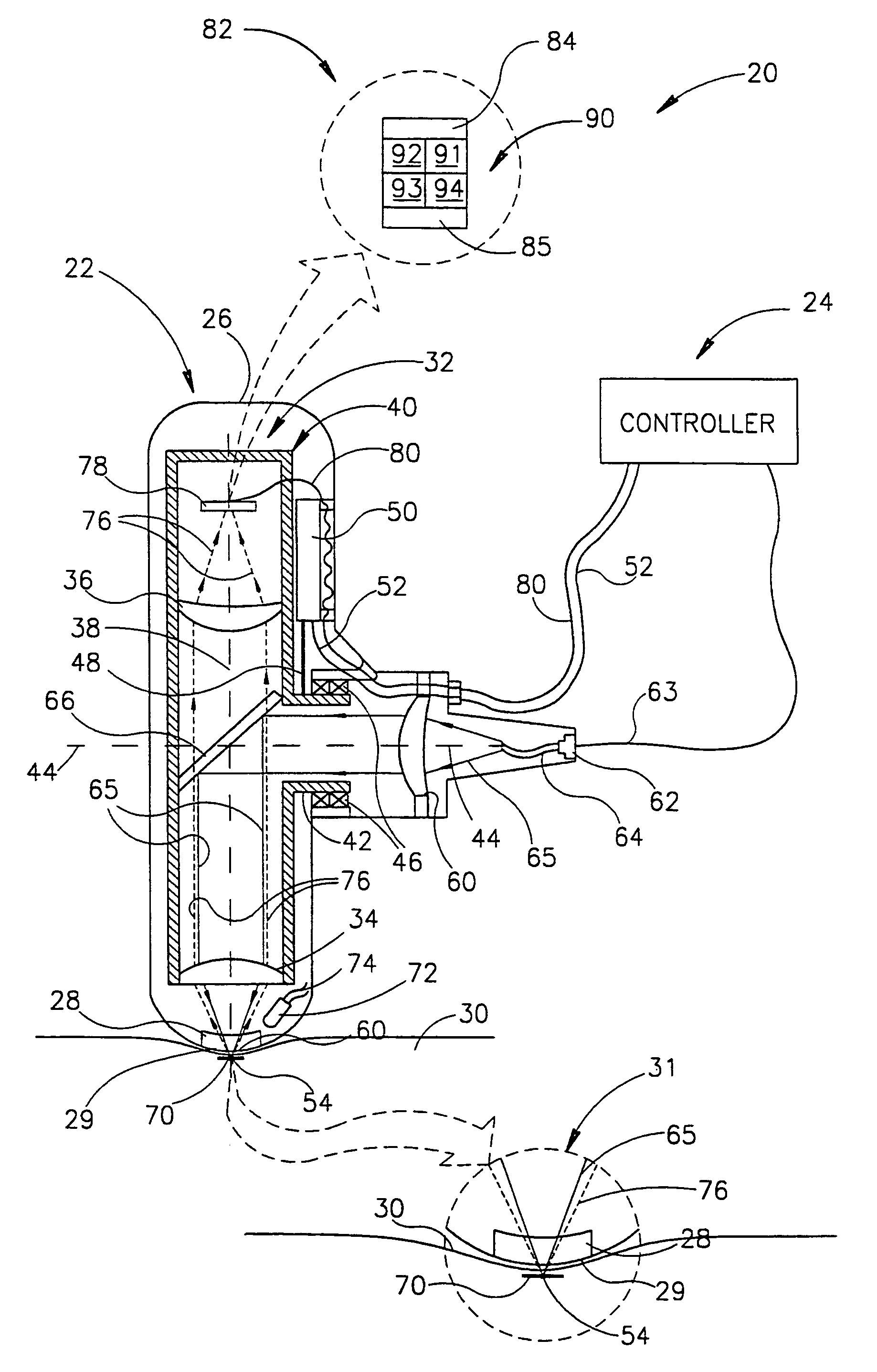
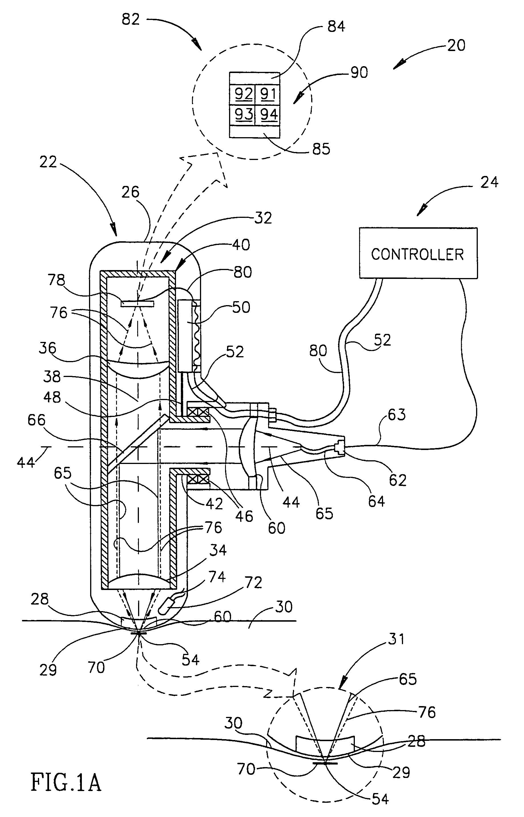
[0062]FIG. 1A schematically shows a laser system 20, in accordance with a preferred embodiment of the present invention, comprising a hand unit 22 and a controller 24. Hand unit 22 is shown in a cutaway cross-section view. It should be noted that whereas controller 24 is shown separate from hand unit 22, in most preferred embodiments, controller 24 is mounted on or inside hand unit 22. In addition, energy to power hand unit 22 may come from an external power supply or preferably from an appropriate portable power supply mounted inside hand unit 22.

[0063]Hand unit 20 preferably comprises a housing 26 having a window 28. Window 28 has a surface 29 that is pressed to the skin 30 of a patient. Surface 29 and skin 30 are shown separated by a small distance for clarity of presentation and are shown magnified in an insert 31. Hand unit 20 comprises a microscope 32 mounted inside housing 26. Microscope 32 comprises an objective lens 34, an ocular lens 36 and an optic axis 38. Objective lens...


PUM


Abstract

A laser system for treating features on the skin of a patient with laser light comprising: an imaging subsystem that locates features on the skin to be treated; a laser; laser optics that focuses light from the laser onto a feature located by the imaging subsystem; and a controller that when a feature is located, controls the laser to radiate a pulse of laser light that is focused by the laser optics to a spot localized about the feature.

Description

RELATED APPLICATIONS[0001]The present application is a US National application of PCT / IL99 / 00279, filed 25 May 1999.FIELD OF THE INVENTION[0002]The invention relates to laser devices and especially to laser devices used for cosmetic and surgical treatment of the skin.BACKGROUND OF THE INVENTION[0003]The use of lasers in corrective and cosmetic surgery procedures is well known. In these procedures light from a laser comprised in an appropriate mechanical-optical system causes a desired cosmetic or surgical change in a region of tissue by delivering to the region an amount of energy sufficient to effect the change. A common problem often encountered in these procedures is to deliver the energy to the region, hereinafter referred to as a “target”, without delivering energy to tissue surrounding the region that might damage the surrounding tissue. Many prior art medical laser systems do not solve this problem satisfactorily and often deliver substantial amounts of unwanted and unneeded ...

Claims


Application Information

Patent Timeline
IPC IPC(8): A61B18/18A61B18/20A61N5/067A61B17/00
CPCA61B18/203A61B18/20A61B2018/2085A61B2018/00452A61B2018/00904A61B2017/00057A61B2018/20351A61B2018/20355A61B2018/2065
Inventor SHARON, UZI
Owner ITL OPTRONICS
Why Eureka
Try Eureka