Triaxial antenna for microwave tissue ablation

a triaxial antenna and tissue ablation technology, applied in the field of medical instruments for ablating tissue, can solve the problems of limited power, mwa can produce greater and more rapid heating, and current mfa equipment produces relatively small lesions, so as to improve the tuning of the antenna, reduce the heating of the feeder line, and reduce the effect of reflected energy

Active Publication Date: 2006-09-05
WISCONSIN ALUMNI RES FOUND
View PDF24 Cites 149 Cited by
  • Summary
  • Abstract
  • Description
  • Claims
  • Application Information

AI Technical Summary

Benefits of technology

[0004]The present invention provides a triaxial microwave probe design for MWA where the outer conductor allows improved tuning of the antenna to reduce reflected energy through the feeder line. This improved tuning reduces heating of the feeder line allowing more power to be applied to the tissue and / or a smaller feed line to be used. Further, the outer conductor may slide with respect to the inner conductors to permit adjustment of the tuning in vivo to correct for effects of the tissue on the tuning.
[0005]Specifically, the present invention provides a probe for microwave ablation having a first conductor and a tubular second conductor coaxially around the first conductor but insulated therefrom. A tubular third conductor is fit coaxially around the first and second conductors. The first conductor may extend beyond the second conductor into tissue when a proximal end of the probe is inserted into a body for microwave ablation. The second conductor may extend beyond the third conductor into the tissue to provide improved tuning of the probe limiting power dissipated in the probe outside of the exposed portions of the first and second conductors.
[0006]Thus, it is one object of at least one embodiment of the invention to provide improved tuning of an MWA device to provide greater power to a lesion without risking damage to the feed line or burning of tissue about the feed line and / or to allow smaller feed lines in microwave ablation.
[0011]It is another object of at least one embodiment of the invention to provide a probe that facilitates tuning of the probe in tissue by sliding the first and second conductors inside of a separate introducer needle.
[0015]Thus, it is another object of at least one embodiment of the invention to provide a method of rapidly setting the probe that allows for tuning after a coarse setting is obtained.

Problems solved by technology

However, MWA can produce greater and more rapid heating and can easily support the use of multiple probes because current flow between the probes can be limited.
Unfortunately, current MFA equipment produces relatively small lesions because of practical limits in power and treatment time.
Power is limited by the current carrying capacity of the small gauge feeder line as it passes through the patient to the site of the necrosis.
Larger feeder lines are undesirable because they are not easily inserted percutaneously.
Heating of the feeder line at high powers can also lead to burns around the insertion point of the MWA probe.

Method used


Image

  • Triaxial antenna for microwave tissue ablation
  • Triaxial antenna for microwave tissue ablation

Examples


Embodiment Construction

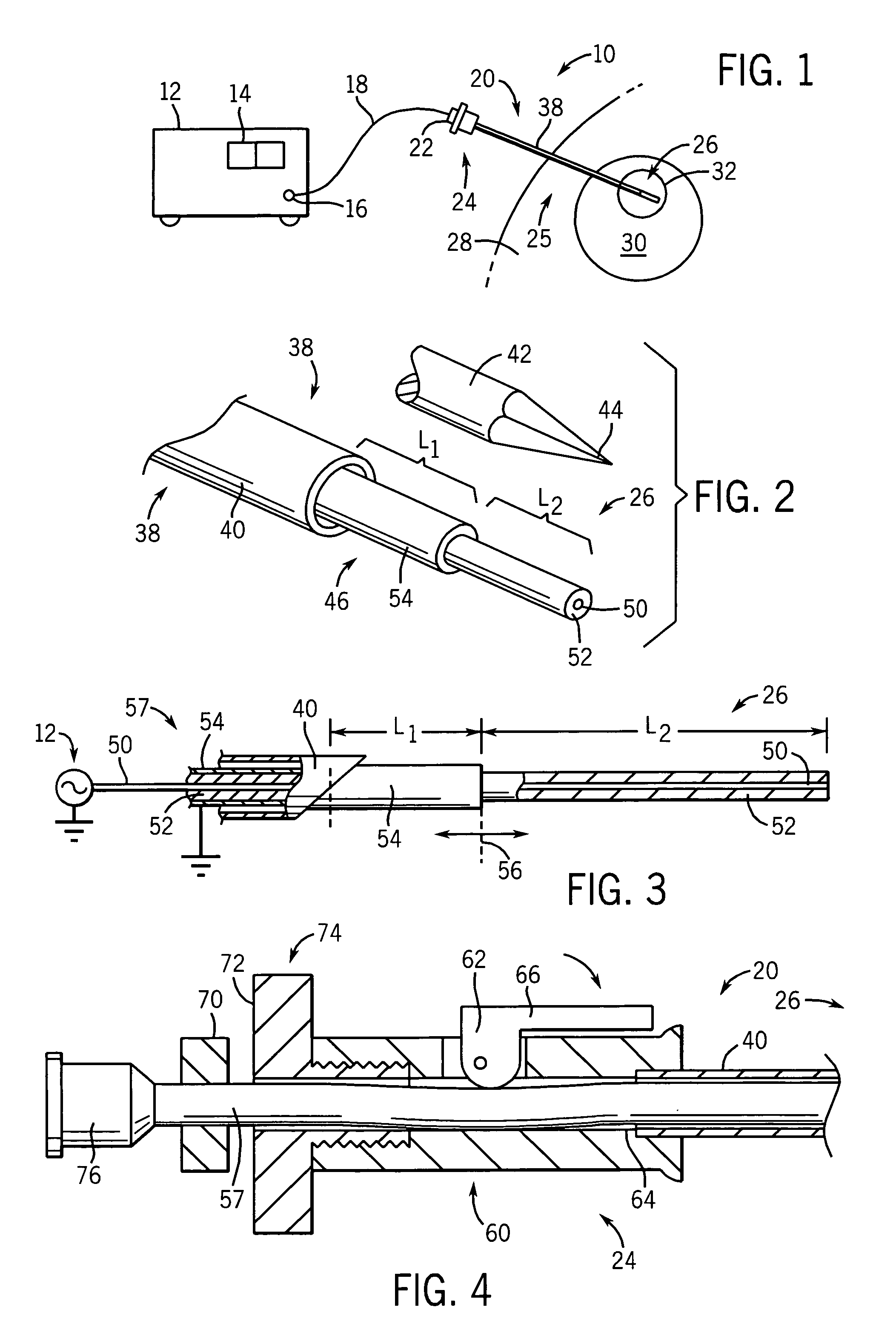
[0023]Referring now to FIG. 1, a microwave ablation device 10 per the present invention includes a microwave power supply 12 having an output jack 16 connected to a flexible coaxial cable 18 of a type well known in the art. The cable 18 may in turn connect to a probe 20 via a connector 22 at a distal end 24 of the probe 20.

[0024]The probe 20 provides a shaft 38 supporting at a proximal end 25 an antenna portion 26 which may be inserted percutaneously into a patient 28 to an ablation site 32 in an organ 30 such as the liver or the like.

[0025]The microwave power supply 12 may provide a standing wave or reflected power meter 14 or the like and in the preferred embodiment may provide as much as 100 watts of microwave power of a frequency of 2.45 GHz. Such microwave power supplies are available from a wide variety of commercial sources including as Cober-Muegge, LLC of Norwalk, Conn., USA.

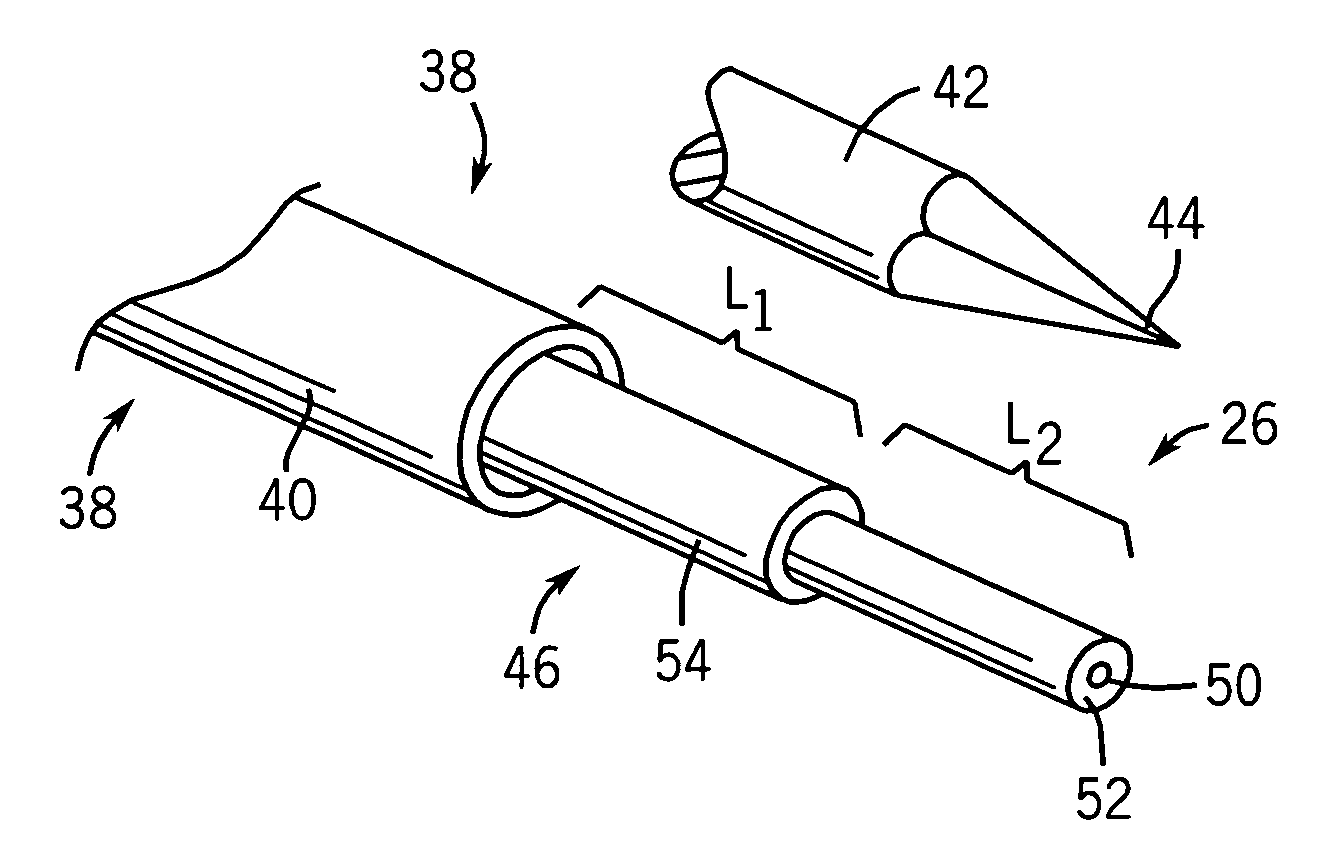
[0026]Referring now to FIGS. 1 and 2, generally a shaft 38 of the probe 20 includes an electrically ...


PUM


Abstract

An improved antenna for microwave ablation uses a triaxial design which reduces reflected energy allowing higher power ablation and / or a smaller diameter feeder line to the antenna.

Description

CROSS-REFERENCE TO RELATED APPLICATIONSSTATEMENT REGARDING FEDERALLY SPONSORED RESEARCH OR DEVELOPMENTBACKGROUND OF THE INVENTION[0001]The present invention relates to medical instruments for ablating tissue, and in particular to a microwave probe for ablation of tumors and the like.[0002]Microwave ablation (MWA), like radio frequency ablation (RFA), uses localized heating to cause tissue necrosis. However, MWA can produce greater and more rapid heating and can easily support the use of multiple probes because current flow between the probes can be limited. The mode of heating in MWA also eliminates ground pads and charring concerns.[0003]Unfortunately, current MFA equipment produces relatively small lesions because of practical limits in power and treatment time. Power is limited by the current carrying capacity of the small gauge feeder line as it passes through the patient to the site of the necrosis. Larger feeder lines are undesirable because they are not easily inserted percut...

Claims


Application Information

Patent Timeline
Patent Type & Authority Patents(United States)
IPC IPC(8): A61B18/04A61B18/18A61F2/00
CPCA61B18/1815A61B18/18
Inventor VAN DER WELDE, DANIEL W.
Owner WISCONSIN ALUMNI RES FOUND
Why Eureka
Try Eureka