
Radio frequency ablation cooling shield

a technology of radio frequency ablation and cooling shield, which is applied in the field of structure and use of ablation, can solve the problems of high likelihood of re-occurren

Inactive Publication Date: 2006-09-05
BOSTON SCI SCIMED INC
View PDF18 Cites 96 Cited by
  • Summary
  • Abstract
  • Description
  • Claims
  • Application Information

AI Technical Summary

Benefits of technology

The present invention provides a medical assembly for cooling tissue during ablation procedures. The assembly includes an elongated member and an inflatable cooling balloon mounted on the elongate member. The balloon can be placed between target tissue and non-target tissue to protect the non-target tissue during treatment. The assembly can also include a needle array that can be actively cooled to protect non-target tissue during ablative treatment. The needle array can be embedded within the non-target tissue or placed between two organs to conduct thermal energy away from the non-target tissue. The invention provides a more efficient and safe method for ablation procedures.

Problems solved by technology

In many cases, to prevent or reduce the risk of thermally injuring the vital organs or tissue, the physician will opt to discontinue the procedure, or prematurely stop the procedure, resulting in a high likelihood of re-occurrence.

Method used


Image

  • Radio frequency ablation cooling shield
  • Radio frequency ablation cooling shield
  • Radio frequency ablation cooling shield

Examples


Embodiment Construction

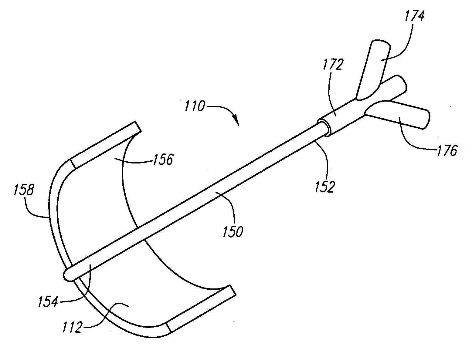
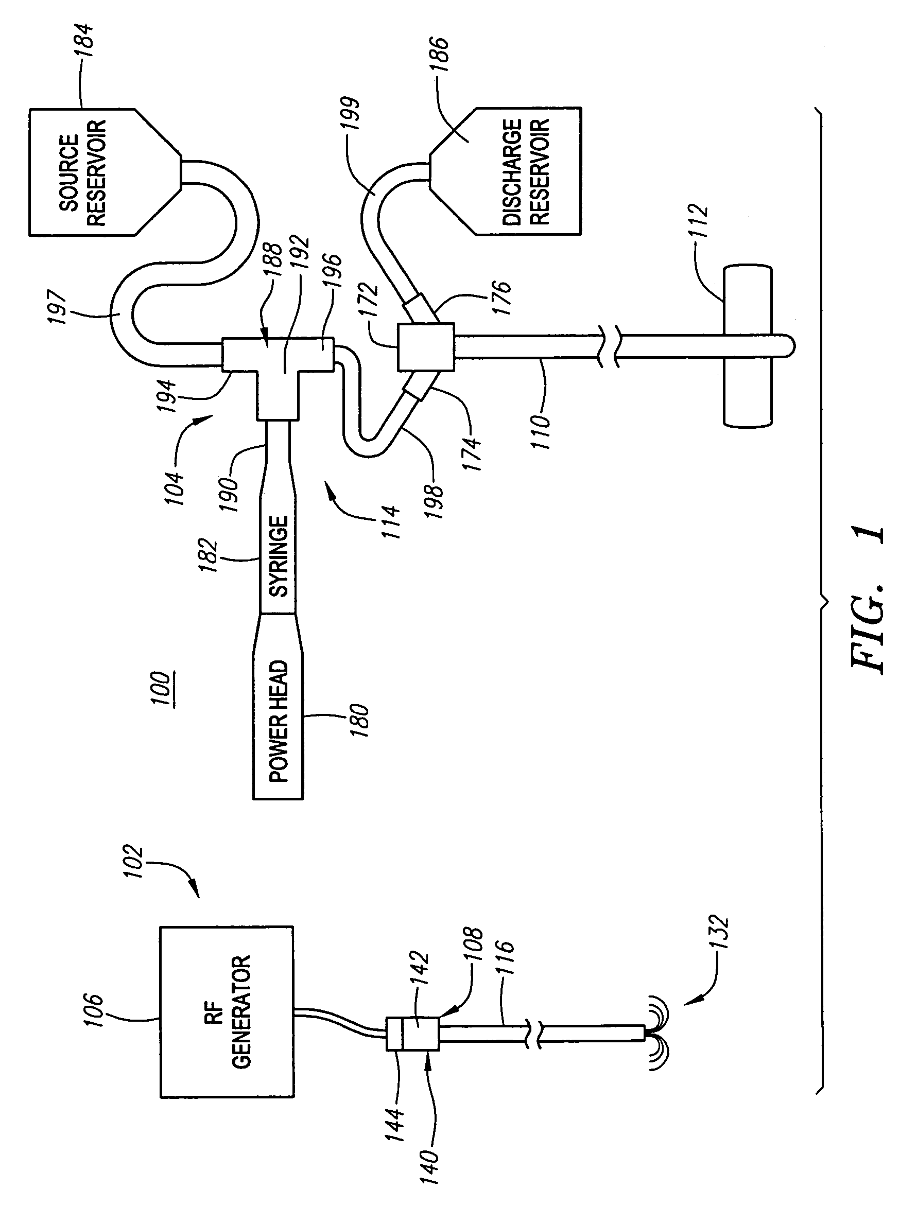
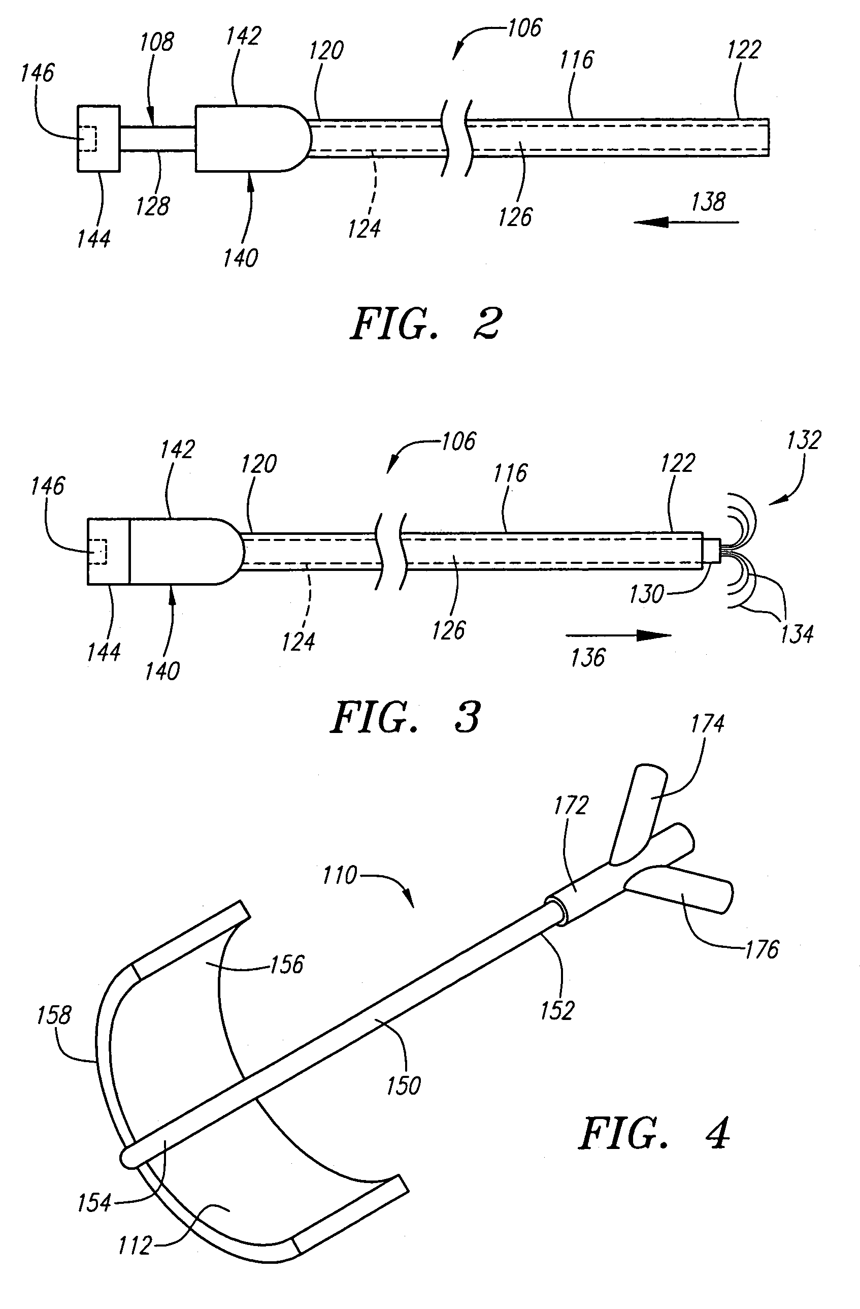
[0034]FIG. 1 illustrates a tissue treatment system 100 constructed in accordance with a preferred embodiment of the present inventions. The tissue treatment system 100 comprises a tissue ablation subsystem 102, which generally includes an ablation probe assembly 106 configured for introduction into the body of a patient for ablative treatment of target tissue (e.g., a tumor), and a radio frequency (RF) generator 108 configured for supplying RF energy to the ablation probe assembly 106 in a controlled manner. The tissue treatment system 100 further comprises a tissue cooling subsystem 104, which generally includes a cooling probe 110 with an associated active cooling shield 112 configured for being effectively placed in contact with non-target tissue (e.g., a vital organ adjacent the tumor), and an active cooling unit 114 configured for actively removing thermal energy away from the cooling shield 112, and thus, the non-target tissue, during the ablation procedure.

[0035]Referring spe...


PUM


Abstract

A medical assembly and method are provided to effectively treat abnormal tissue, such as, a tumor. The target tissue is thermally ablated using a suitable source, such as RF or laser energy. A cooling shield is placed in contact with non-target tissue adjacent the target tissue, and actively cooled to conduct thermal energy away from the non-target tissue. In one method, the cooling shield can be placed between two organs, in which case, one of the two organs can comprise the target tissue, and the other of the two organs can comprise the non-target tissue. In this case, the cooling shield may comprise an actively cooled inflatable balloon, which can be disposed between the two organs when deflated, and then inflated. The inflatable balloon can be actively cooled by pumping a cooling medium through it. In another method, the cooling shield can be embedded within the non-target tissue. In this case, the cooling shield can comprise one or more needles. If a plurality of needles is used, they can be embedded into the non-target tissue in a series, e.g., a rectilinear or curvilinear arrangement. The needle(s) can be actively cooled by pumping a cooling medium through them.

Description

FIELD OF THE INVENTION[0001]The field of the invention generally relates to the structure and use of ablation to treat tissue abnormalities in a patient, and more particularly, to the use of radio frequency (RF) electrosurgical probes for the treatment of such tissue.BACKGROUND OF THE INVENTION[0002]The delivery of radio frequency (RF) energy to target regions within tissue is known for a variety of purposes of particular interest to the present inventions. In one particular application, RF energy may be delivered to diseased regions (e.g., tumors) in tissue for the purpose of tissue necrosis. RF ablation of tumors is currently performed within one of two core technologies.[0003]The first technology uses a single needle electrode, which when attached to a RF generator, emits RF energy from the exposed, uninsulated portion of the electrode. This energy translates into ion agitation, which is converted into heat and induces cellular death via coagulation necrosis. The second technolog...

Claims


Application Information

Patent Timeline
Patent Type & Authority Patents(United States)
IPC IPC(8): A61B18/18A61F7/00A61M29/00A61B18/00A61B19/00
CPCA61B19/40A61B18/14A61B2018/00017A61B2018/00023A61B2018/00577A61B2019/4081A61B2018/00029A61B2019/4045A61B90/04A61B2090/0445A61B2090/0481A61B18/1477A61B2018/00005
Inventor GARABEDIAN, ROBERT J.RIOUX, ROBERT F.
Owner BOSTON SCI SCIMED INC
Learn More