MRI method and apparatus for faster data acquisition or better motion artifact reduction

a technology of motion artifact reduction and data acquisition, applied in the field of magnetic resonance imaging methods and apparatuses, can solve the problems of patient motion, relatively long data acquisition time, and require an additional /2 imaging time, and achieve the effect of reducing the disadvantage of longer data acquisition tim

Inactive Publication Date: 2006-09-05
SIEMENS HEALTHCARE GMBH
View PDF5 Cites 39 Cited by
  • Summary
  • Abstract
  • Description
  • Claims
  • Application Information

AI Technical Summary

Benefits of technology

[0012]An object of the present invention is to provide a method for operating a magnetic resonance imaging apparatus which takes advantage of the motion artifact reduction achieved with the PROPELLER technique, but alleviates the disadvantage of the longer time for data acquisition associated with the PROPELLER technique.
[0014]The above object is achieved in accordance with the principles of the present invention in a method and apparatus wherein the magnetic resonance raw data are acquired from the subject using a partial acquisition technique, and are entered into k-space according to the PROPELLER technique. The more rapid data acquisition that is achieved by the use of PAT, such as partial parallel acquisition (PPA), compensates for the additional imaging time associated with the PROPELLER technique, due to the oversampling of the central region in k-space.
[0015]In a conventional PROPELLER data acquisition, PROPELLER data are collected in k-space in a number of strips, with each strip consisting of L parallel linear trajectories. Each strip is rotated in k-space by an angle, so that the total dataset spans a circle in k-space. In accordance with the inventive method and apparatus, each strip is acquired according to a parallel acquisition technique, thereby reducing the amount of time needed for the acquisition of each strip. The parallel acquisition technique that is used can operate so that only a portion of L lines, for example, L / 2, is acquired in each strip. Alternatively, the width of each strip can be expanded.
[0018]The method and apparatus of the invention have several advantages. The PROPELLER technique proceeds more quickly because only a part of the conventionally acquired L lines is acquired in each strip in accordance with the invention. Nevertheless, the excellent motion correction achieved by PROPELLER is retained. The data acquisition time is comparable to that of non-PROPELLER scans. In the embodiment wherein the propeller strips are wider, better motion correction is achieved than with a conventional propeller technique, due to more accurate low-resolution phase maps. In this embodiment, the data acquisition time is the same, or may even be shorter, than that of a conventional PROPELLER scan.

Problems solved by technology

Particularly in the case of cardiac MRI, two problems are persistent, namely patient motion, including respiratory motion, during data acquisition, and a relatively long data acquisition time.
Such problems also exist in other types of MRI such as, for example, functional MRI (fMRI).
The PROPELLER technique has proven to be a good solution for reducing motion artifacts, but it requires an additional π / 2 imaging time, due to the necessity of oversampling the central region of k-space.

Method used


Image

  • MRI method and apparatus for faster data acquisition or better motion artifact reduction
  • MRI method and apparatus for faster data acquisition or better motion artifact reduction
  • MRI method and apparatus for faster data acquisition or better motion artifact reduction

Examples


Embodiment Construction

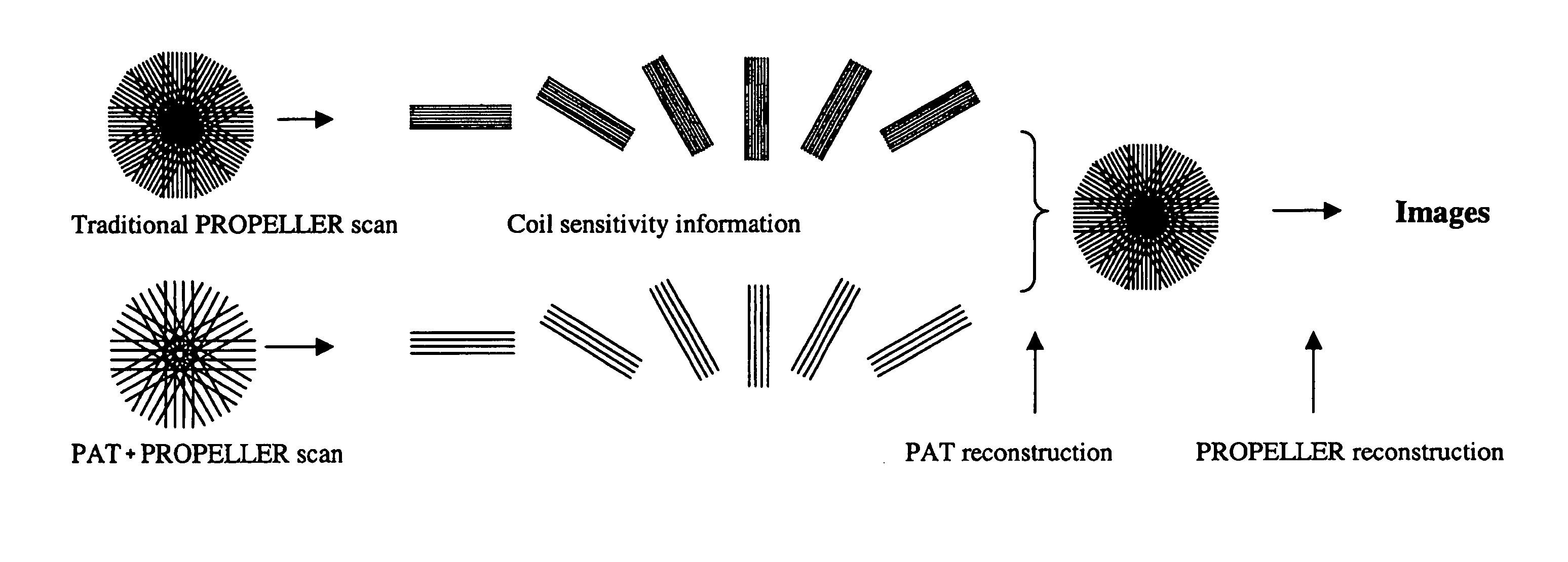
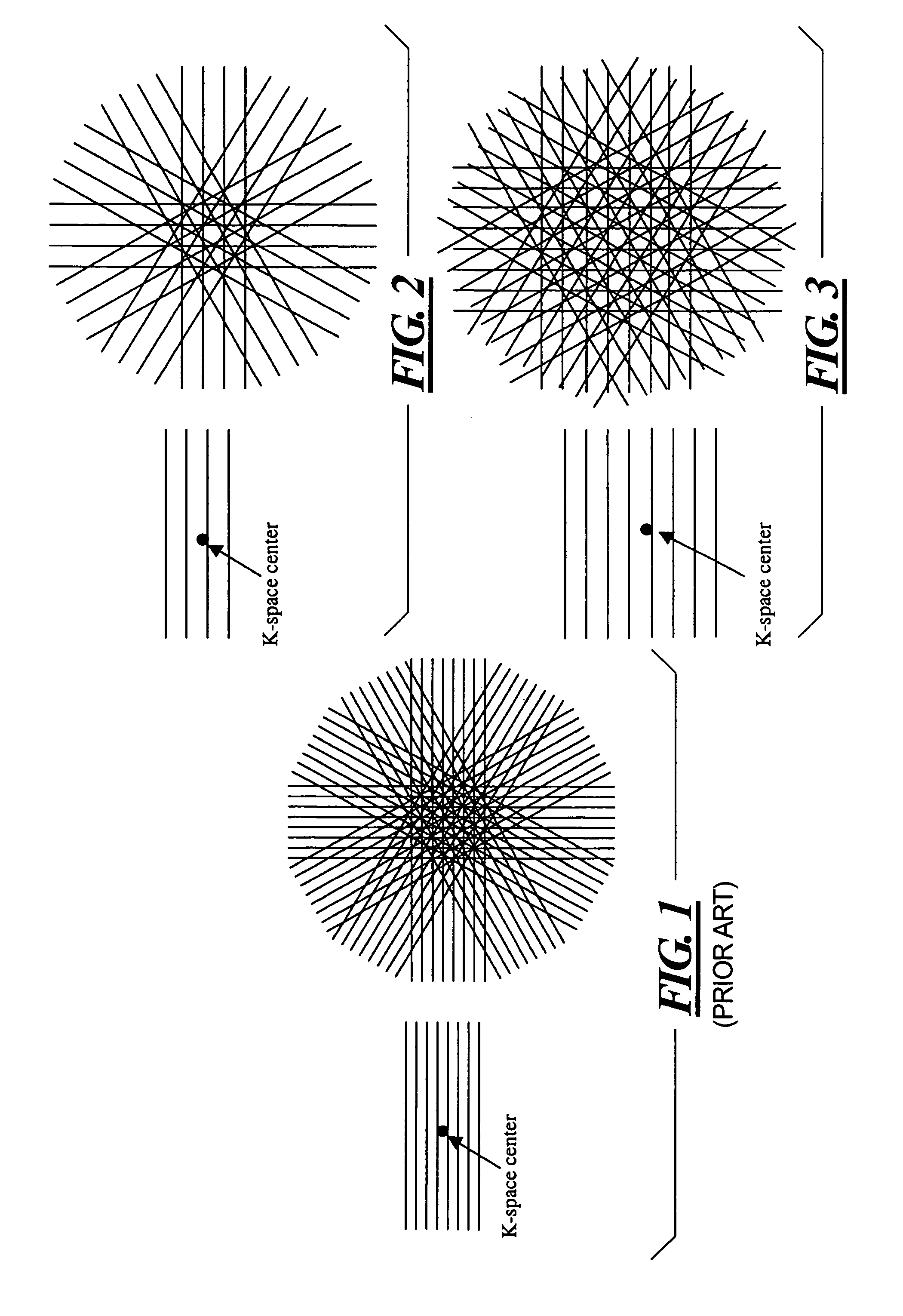
[0026]FIG. 1 schematically illustrates the concept underlying a conventional PROPELLER scan. Data are acquired in k-space in N strips, each consisting of L parallel lines, corresponding to the L lowest frequency phase-encoding lines in any Cartesian-based data acquisition technique. Each strip is rotated in k-space by an angle a=π / n, so that the total dataset spans a circle in k-space. If a matrix having diameter M is desired, then L and N are chosen so that L·N−M·π / 2. The central circle in k-space, having a diameter L, is acquired for each of the N strips, which are respectively used to form N low-resolution images. These low-resolution images are compared to each other to remove in-plane displacement and phase errors, which are slowly varying in the spatial domain. These factors are corrected for each strip. A suitable technique such as cross-correlation is employed to determine which strips were acquired with significant through-plane displacement. As the data are combined in k-s...


PUM


Abstract

In a method and apparatus for generating a magnetic resonance image, raw magnetic resonance data are acquired from a subject for each of a number of PROPELLER strips using, for each strip, multiple magnetic resonance reception coils in a partial acquisition technique (PAT), and the raw data in said PROPELLER strips are entered into k-space according to the PROPELLER scan. A PAT reconstruction of the data in k-space is conducted dependent on the respective sensitivities of the reception coils, and a PROPELLER reconstruction of the data in k-space is conducted after the PAT reconstruction for generating a magnetic resonance image of the subject.

Description

BACKGROUND OF THE INVENTION[0001]1. Field of the Invention[0002]The present invention is directed to a method and an apparatus for magnetic resonance imaging (MRI), and in particular to such a method and apparatus making use of the known PROPELLER technique.[0003]2. Description of the Prior Art[0004]Magnetic resonance imaging (MRI), also known as magnetic resonance tomography (MRT), is a known technique for obtaining images of the inside of the body of an object under investigation, such as a patient. For this purpose, a magnetic resonance apparatus has a space for receiving the examination subject. A basic field magnet system of the apparatus generates a static magnetic field in an imaging volume within the examination space that is as homogenous as possible. This basic magnetic field orders or aligns the nuclear spins of the nuclei in the subject, which were previously randomly oriented. A radio-frequency (RF) antenna system is also a part of the apparatus, and includes an RF tran...

Claims


Application Information

Patent Timeline
Patent Type & Authority Patents(United States)
IPC IPC(8): G01V3/00
CPCG01R33/561G01R33/4824
Inventor ZHANG, QIANGSIMONETTI, ORLANDO
Owner SIEMENS HEALTHCARE GMBH
Why Eureka
Try Eureka