[0006]An object of the present invention is to provide a hydrodynamic bearing that prevents in gaps the agglomeration of
microbubbles intruding inside a
lubricant by allowing them to easily escape out of the gaps, and reliably maintains a
lubricant-filled condition of the whole of radial dynamic-pressure generating grooves and thrust dynamic-pressure generating grooves, thereby ensuring high reliability.
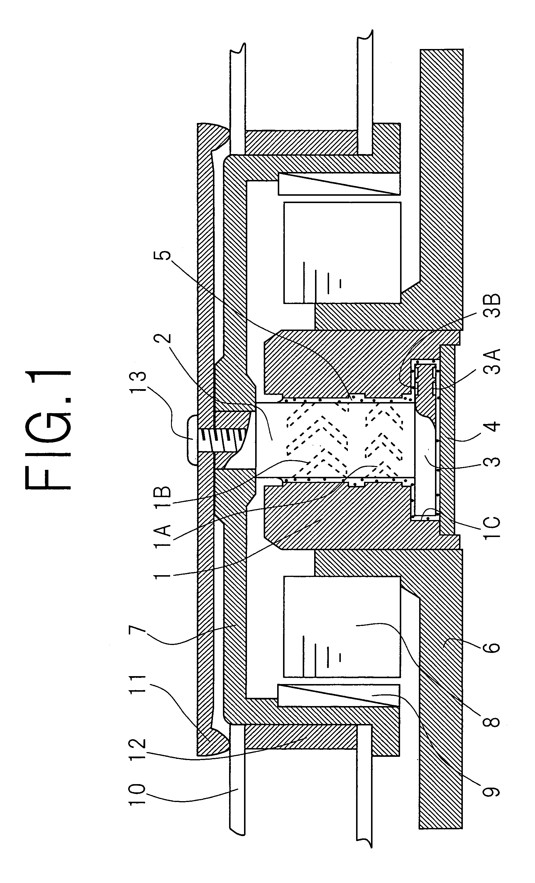
[0019]In the above-described hydrodynamic bearing according to the present invention, the lubricant flows along the radial dynamic-pressure generating grooves and is concentrated in predetermined regions when the shaft or the sleeve revolves around the shaft. As a result, pressure in the radial direction of the shaft rises in gaps between the shaft and the sleeve. This pumping effect maintains stable spacing between the shaft and the sleeve, and thus, the axis of rotation of the shaft or the sleeve does not substantially shift in the radial direction of the shaft. Similarly, the lubricant flows along the thrust dynamic-pressure generating grooves and is concentrated in predetermined regions. As a result, pressure in the axial direction of the shaft rises on surfaces of the flange. This pumping effect maintains stable spacing between the flange and the hollow of the sleeve and stable spacing between the flange and the thrust plate. Therefore, the axis of rotation of the shaft or the sleeve does not substantially tilt from the axial direction of the shaft. Thus, the above-described hydrodynamic bearing according to the present invention maintains high-speed revolutions of the shaft or the sleeve stable with high precision.
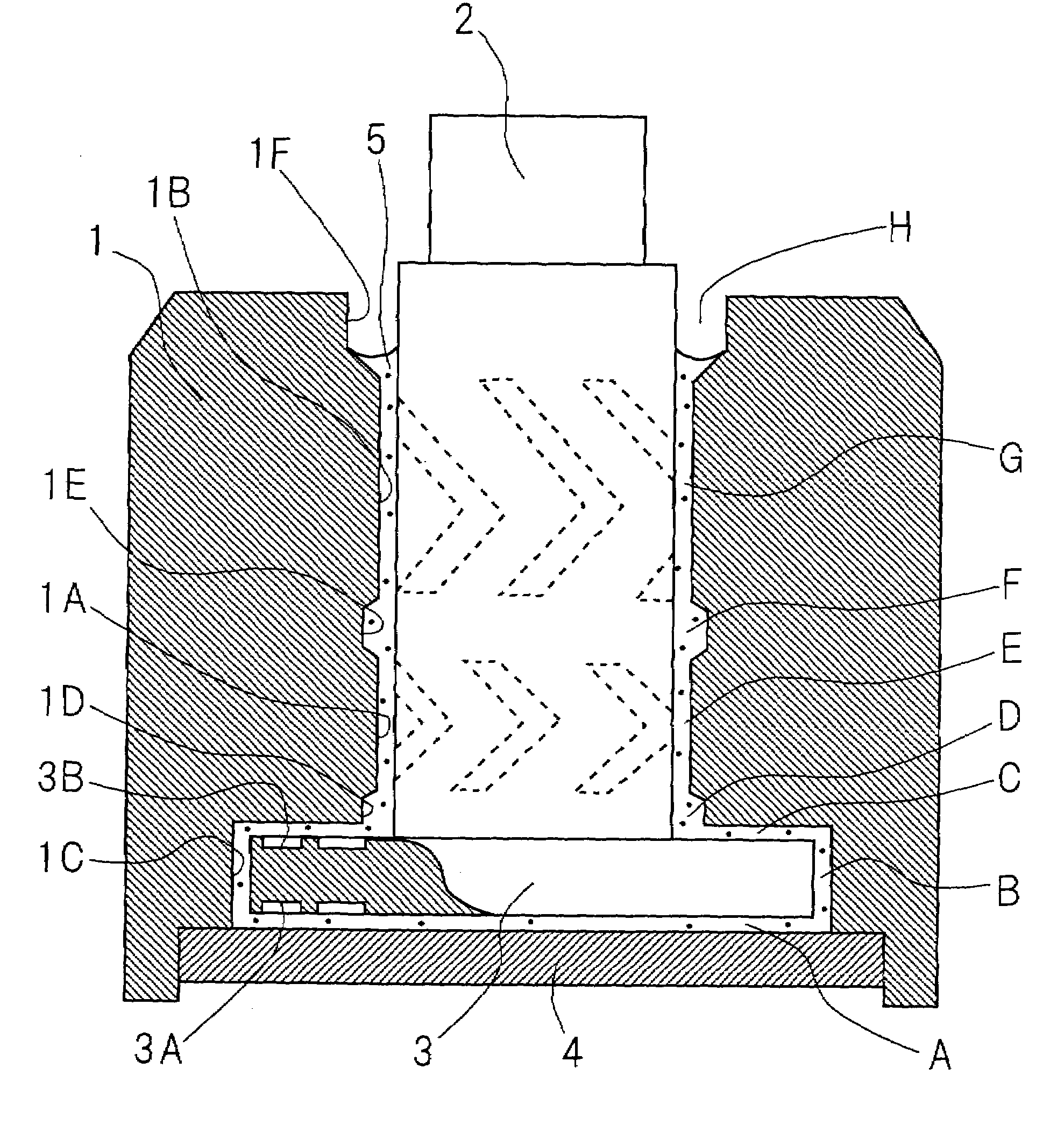
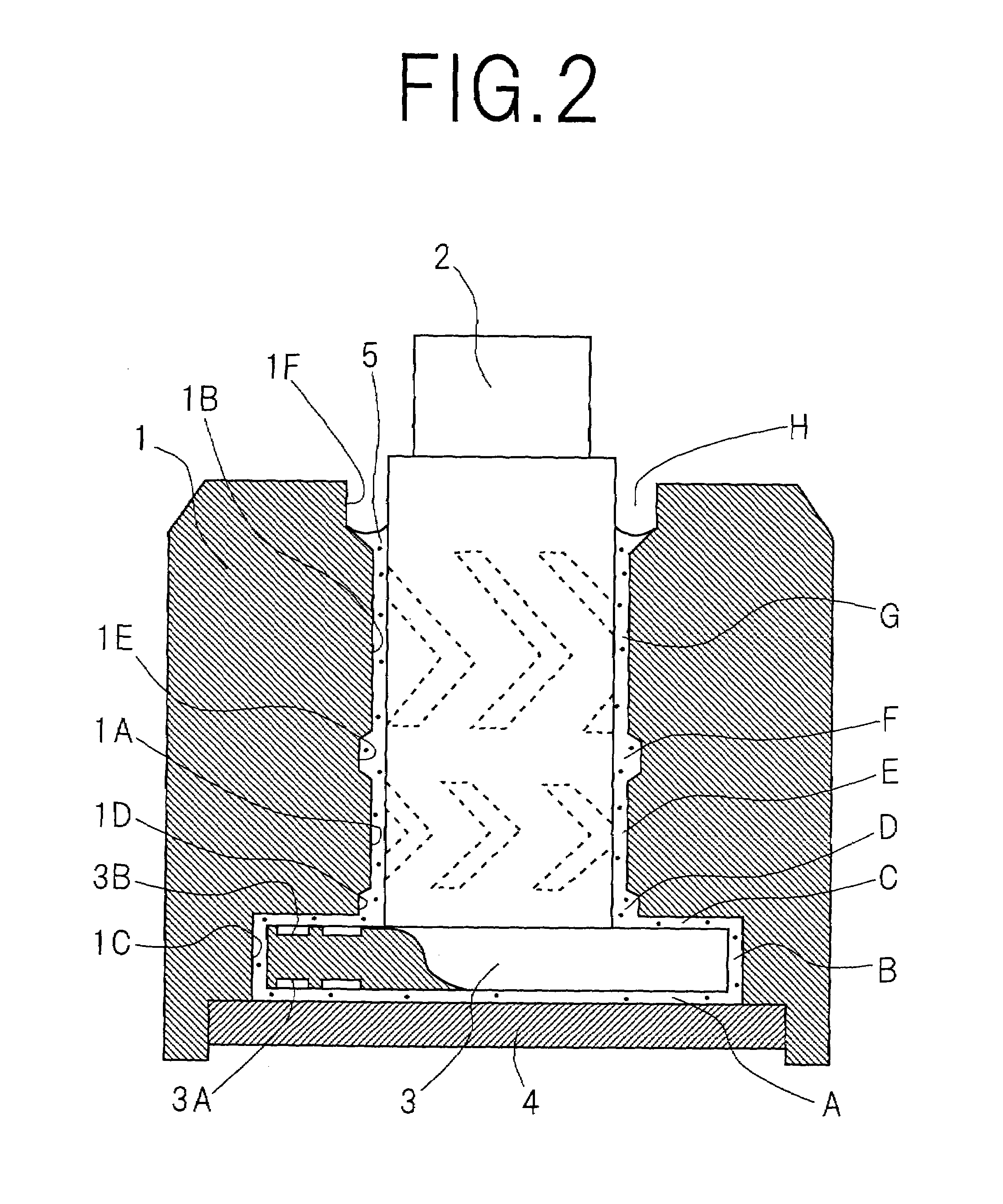
[0020]In the above-described hydrodynamic bearing according to the present invention, gaps among the sleeve, the shaft, the flange, and the thrust plate are set as described above. More specifically, the gaps over the thrust dynamic-pressure generating grooves and their vicinities are narrower than the surrounding gaps. Furthermore, the surrounding gaps are narrower than the gaps in the second opening end of the sleeve and its vicinity. In addition, the gaps over the radial dynamic-pressure generating grooves and their vicinities are narrower than the gaps in the second opening end of the sleeve and its vicinity. In that case, the sealing force of lubricant is the strongest over the thrust dynamic-pressure generating grooves and their vicinities, next stronger in the gaps surroundings the flange, and the weakest in the second opening end of the sleeve and its vicinity. Furthermore, the sealing force over the radial dynamic-pressure generating grooves and their vicinities is stronger than the sealing force in the second opening end of the sleeve and its vicinity. Such a gradient of sealing force keeps
microbubbles in the lubricant away from the vicinities of the thrust dynamic-pressure generating grooves and the radial dynamic-pressure generating grooves, and, in addition, pushes them back into the second opening end of the sleeve. The
microbubbles, in particular, hardly reach in the vicinity of the perimeter of the flange. Thus, occurrences of the air bubbles due to the agglomeration of the microbubbles are prevented, and leakage of lubricant due to the occurrence and swelling of the air bubbles are avoided. Accordingly, the lubricant keeps covering the whole of the radial dynamic-pressure generating grooves and the thrust dynamic-pressure generating grooves with stability, that is, no so-called lack of
oil film occurs. In other words, the above-described pumping effects are maintained with stability, and thus, spacing between the shaft and the sleeve is maintained with stability. Therefore, the above-described hydrodynamic bearing according to the present invention has high reliability.
[0021]In the above-described hydrodynamic bearing according to the present invention, the radial dynamic-pressure generating grooves may be provided in two regions, a first region near the flange and a second region near the second opening end of the sleeve. In that case, it is preferable that inequalities E<D, E<F, G<D, G<F, and F<H all hold, where E is a distance in the radial direction of the shaft between the shaft and the sleeve in the first region, F is a distance in the radial direction of the shaft between the shaft and the sleeve in an
intermediate region between the first region and the second region, and G is a distance in the radial direction of the shaft between the shaft and the sleeve in the second region. Thereby, the gaps in the first and second regions and their vicinities, that is, the gaps over the radial dynamic-pressure generating grooves and their vicinities, are narrower than the surrounding gaps. Furthermore, the surrounding gaps are narrower, than the gaps in the second opening end of the sleeve and its vicinity. In that case, the sealing force of lubricant is the strongest over the radial dynamic-pressure generating grooves and their vicinities, next stronger in the gaps in an
intermediate region between the second region and the flange and its vicinity, and the gaps in the
intermediate region between the first region and the second region and its vicinity, and the weakest in the second opening end of the sleeve and its vicinity. Such a gradient of sealing force keeps microbubbles in the lubricant away from the vicinities of the radial dynamic-pressure generating grooves, and, in addition, pushes them back into the second opening end of the sleeve. The microbubbles, in particular, hardly accumulate in the intermediate region between the first region and the second region. Thus, occurrences of the air bubbles due to the agglomeration of the microbubbles are prevented, and leakage of lubricant due to the occurrence and swelling of the air bubbles are avoided. Accordingly, the lubricant keeps covering the whole of the radial dynamic-pressure generating grooves with stability, that is, no so-called lack of
oil film occurs. In other words, the above-described, radial pumping effect is maintained with stability, and thus, spacing between the shaft and the sleeve is maintained with stability. Therefore, the above-described hydrodynamic bearing according to the present invention has still higher reliability.
[0022]In the above-described hydrodyamic bearing according to the present invention, preferably, the lubricant is composed of one of
oil and grease, and shows a kinematic
viscosity of at least 4×10⁻⁶ m2 / s at 40 degrees centigrade. Such a lubricant remarkably reduces a rate of the intrusion of
air bubble. For example, diester-based or
polyester-based lubricant is suitable for the above-described lubricant. The utilization of such a lubricant further effectively prevents leakage of lubricant due to the occurrence and swelling of air bubbles. Accordingly, the above-described hydrodynamic bearing according to the present invention has still higher reliability.
[0023]The above-described hydrodynamic bearing according to the present invention has high reliability as described above. When a disk recording / reproducing apparatus is equipped with the hydrodynamic bearing, the revolution of magnetic disks can further become faster and be further stabilized with higher precision in the disk recording / reproducing apparatus. As a result, increases in capacity and speedups of data transfers can be easily enhanced. In addition, the disk recording / reproducing apparatus can maintain high reliability for a long time.

