
Medium frequency energy supply for rail vehicles

a technology of medium frequency energy supply and rail vehicles, applied in the field of electronic circuits, can solve the problems of reducing the useful space available, disadvantageous transformers, and loss of energy

Inactive Publication Date: 2006-09-05
ALSTOM TRANSPORT TECH SAS
View PDF13 Cites 12 Cited by
  • Summary
  • Abstract
  • Description
  • Claims
  • Application Information

AI Technical Summary

Benefits of technology

The present invention provides an electronic circuit for bidirectional conversion of high input voltage to direct-current output voltage with indirect coupling. The circuit includes a primary converter, a common transformer, and a secondary converter. The design of the circuit ensures operation in the resonant mode even in case of asymmetries of the transformer circuit and of actuation, or of the semiconductors, respectively. The circuit is stable in series production and can be operated with direct-current voltage systems of e.g. 1.5 kV or 3 kV. The circuit has several primary converter sections that are operated directly, by way of a switch and a filter, between an overhead line and a vehicle wheel grounded through a rail. The converter sections are allocated to the respective one of a transformer primary winding of a transformer and are provided with one mains four-quadrant regulator and one transformer primary converter. The transformer has a secondary winding that is allocated to a transformer secondary converter. The technical effects of the invention are saving weight and costs, stable operation, and compatibility with high input voltage systems.

Problems solved by technology

These transformers are disadvantageous because of their overall weight.
This weight occasions loss of energy, which is undesirable since energy costs have to be saved to an ever increasing extent in rail vehicles as well.
Their size, furthermore, considerably reduces the useful space available as complementary components may also be required to cope with other direct current voltage power supplies (1.5 kV DC, 3 kV DC).
The circuit disadvantageously has an additional compensating circuit which is necessary because the converter sections are submitted to different loads.
This makes the system even more complicated which increases the failure probability.
Due to the hard switch operation of the transformer converters, the efficiency of the system is comparatively low.
This may lead to a significantly higher weight than conventional traction drivers (especially with 25 kV).
Taking into account the growth law for transformers, and due to the plurality of individual transformers, the circuit has the disadvantage that it has a high overall weight and that it involves accordingly higher costs compared to a system with but one transformer.
The several secondary converter sections furthermore require considerable expenditure.
The operation of this circuit is unidirectional, i.e., the energy only flows from the overhead line to the vehicle drive so it is not possible to recover the breaking energy.
Another drawback is that the input voltage of the primary converters of the transformer is directly determined by the overhead line.
As a result thereof, operation in the resonant mode cannot be realized if the direct-current output voltage is to remain stable.
Therefore, operation is hard switching with high losses and accordingly low efficiency.
Furthermore, a change in the configuration topology for operation with an alternating voltage or with lower dc voltage is not possible.

Method used


Image

  • Medium frequency energy supply for rail vehicles
  • Medium frequency energy supply for rail vehicles
  • Medium frequency energy supply for rail vehicles

Examples


Embodiment Construction

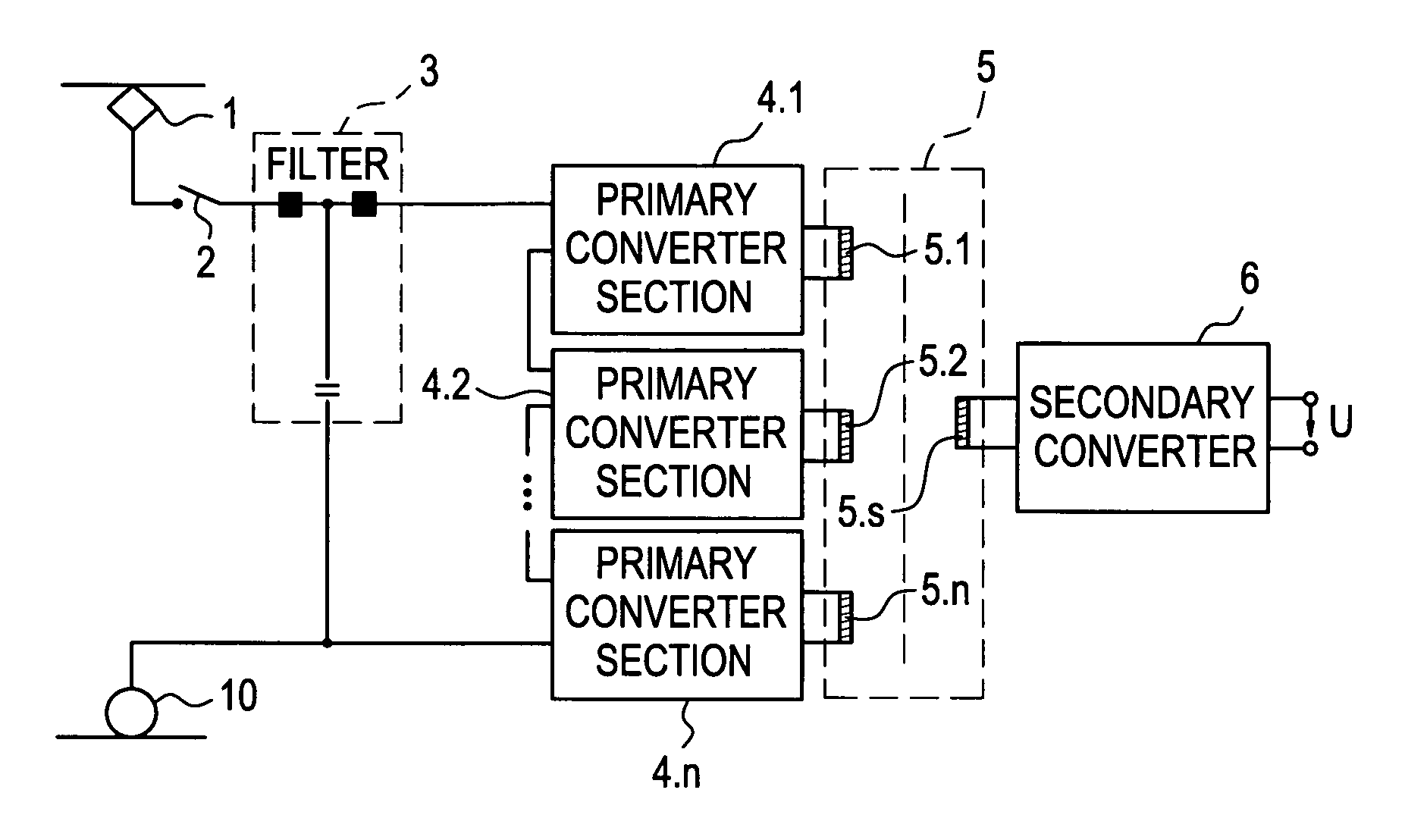
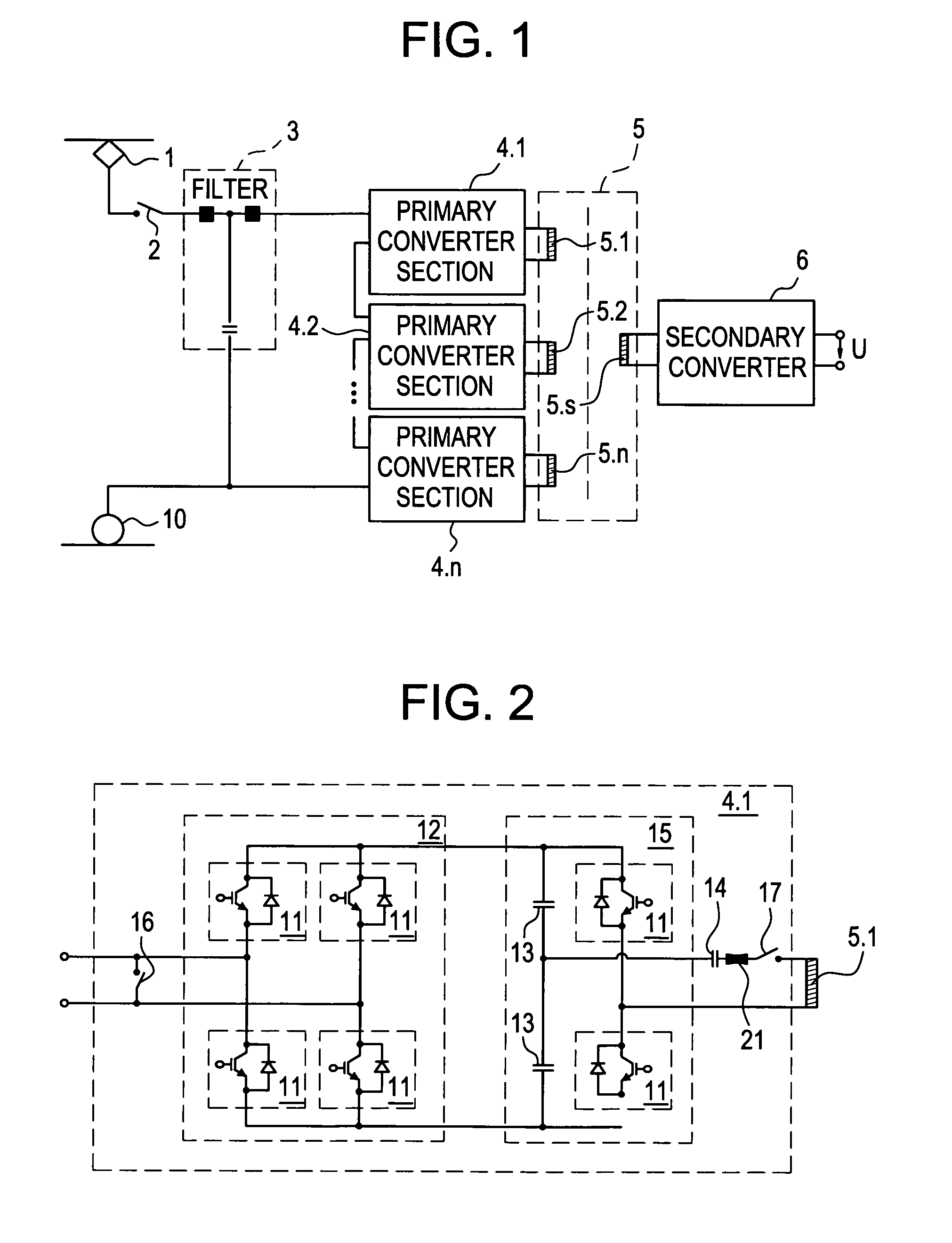
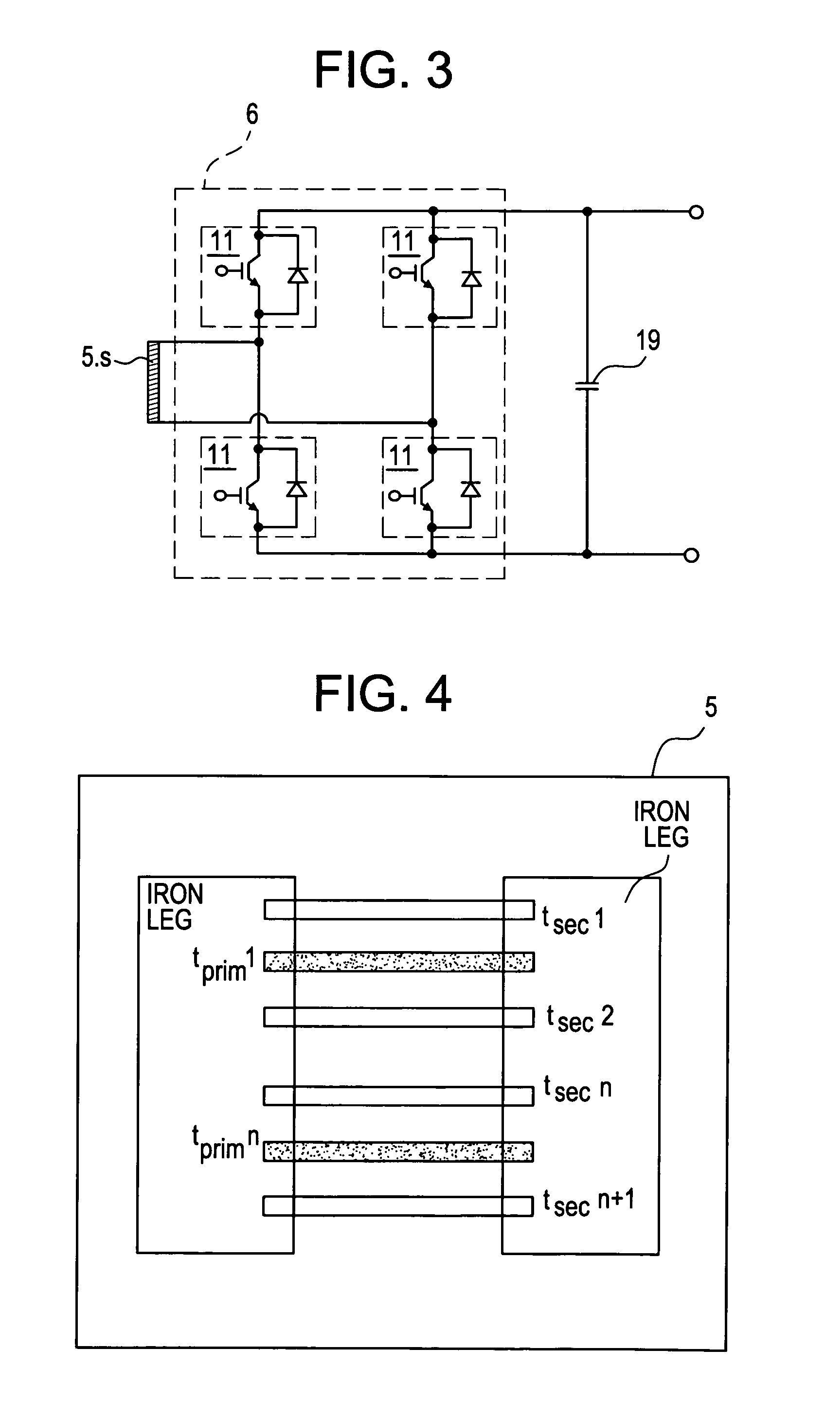
[0024]In a preferred embodiment (FIGS. 1 & 2), the circuit according to the present invention is provided with several primary converter sections 4.1–4.n that are operated directly, by way of a switch 2 and a filter 3, between an overhead line 1 and a vehicle wheel 10 grounded through a rail. The primary converter sections 4.1–4.n are allocated to the respective one of a transformer primary winding 5.1–5.n of a transformer 5 and include one mains four-quadrant regulator 12 in the form of a full bridge with four circuit elements 11 each, each circuit element having one transistor and one free-wheeling diode, and of one half bridge 15 with two circuit elements 11 each, each circuit element having one transistor and one free-wheeling diode and capacitors 13; the half-bridge may be replaced by a full bridge, if so desired. The transformer 5 has a secondary winding that feeds a directly-current voltage intermediate circuit through a secondary converter 6 (FIG. 3).

[0025]In accordance with...


PUM


Abstract

Disclosed is an electronic circuit for the bidirectional conversion of a high input voltage to a direct-current output voltage with indirect coupling, more specifically such a circuit for use in a power supply system for rail vehicles, that is provided with a primary converter, one single common transformer and a secondary converter. The primary converter includes at least three primary converter sections connected in series, the output lines of which are each connected to a respective one of the transformer primary windings.

Description

[0001]This application claims priority of German Patent Application No. 101 03 634.5-32, filed Jan. 27, 2001, the entire contents of which are hereby incorporated by reference.BACKGROUND OF THE INVENTION[0002]1. Field of the Invention[0003]The invention relates to an electronic circuit for bidirectional conversion of a high input voltage to a direct-current output voltage with indirect coupling, more specifically, an electronic circuit for use in a power supply system for rail vehicles.[0004]2. Related Art[0005]Nowadays, 16.7 Hz or 50 Hz transformers are utilized in rail vehicles to convert the high voltage of 15 kV or of 25 kV respectively in the overhead lines of a railroad system to the voltage of nearly 1000 V, whereby the value does not exceed the rating of silicon power components which are able to drive the electric motors. These transformers are disadvantageous because of their overall weight. This weight occasions loss of energy, which is undesirable since energy costs have...

Claims


Application Information

Patent Timeline
Patent Type & Authority Patents(United States)
IPC IPC(8): H02M5/451B60L9/24
CPCB60L9/24B60L2200/26
Inventor FALK, ANDREASVICTOR, MATHIASBACHMANN, GUIDO
Owner ALSTOM TRANSPORT TECH SAS
Learn More