Solution to DQS postamble ringing problem in memory chips

a technology of memory chips and postambles, applied in the field of memory devices, can solve the problems of false data not getting “clocked in” or written into the memory chip, ineffective current buffer-based control of dqs postamble ringing, and inability to accurately control dqs postamble ringing, etc., to achieve faster clock speeds, prevent data corruption, and reduce or eliminate dqs postamble ringing problems

Inactive Publication Date: 2006-09-05
ROUND ROCK RES LLC
View PDF3 Cites 8 Cited by
  • Summary
  • Abstract
  • Description
  • Claims
  • Application Information

AI Technical Summary

Benefits of technology

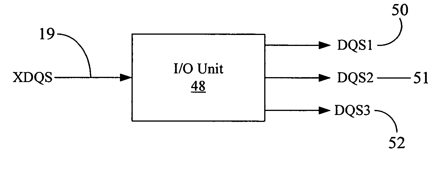
[0018]The system and method of the present disclosure significantly reduce or eliminate DQS postamble ringing problem in modern high-speed memory chips, allowing the memory chips to be operated at significantly faster clock speeds. The external strobe signal (XDQS), which may contain postamble ringing, is used to generate at least two derivative strobe signals therefrom. However, instead of the XDQS signal, the derivative strobe signals are used, in a predetermined order, to clock in or strobe the data to be written into memory cells. Once the last of the derivative strobe signals is activated, and so long as there are no more data writes pending in the command pipe for the next clock cycle, the rising or falling edge of the last derivative strobe signal can be detected to turn off further generation of the strobe signals prior to any onset of postamble ringing on the XDQS signal. Thus, false data may not get “clocked in” or written into the memory chip because of postamble ringing. This prevents data corruption and preserves the integrity of the data written into a memory chip.

Problems solved by technology

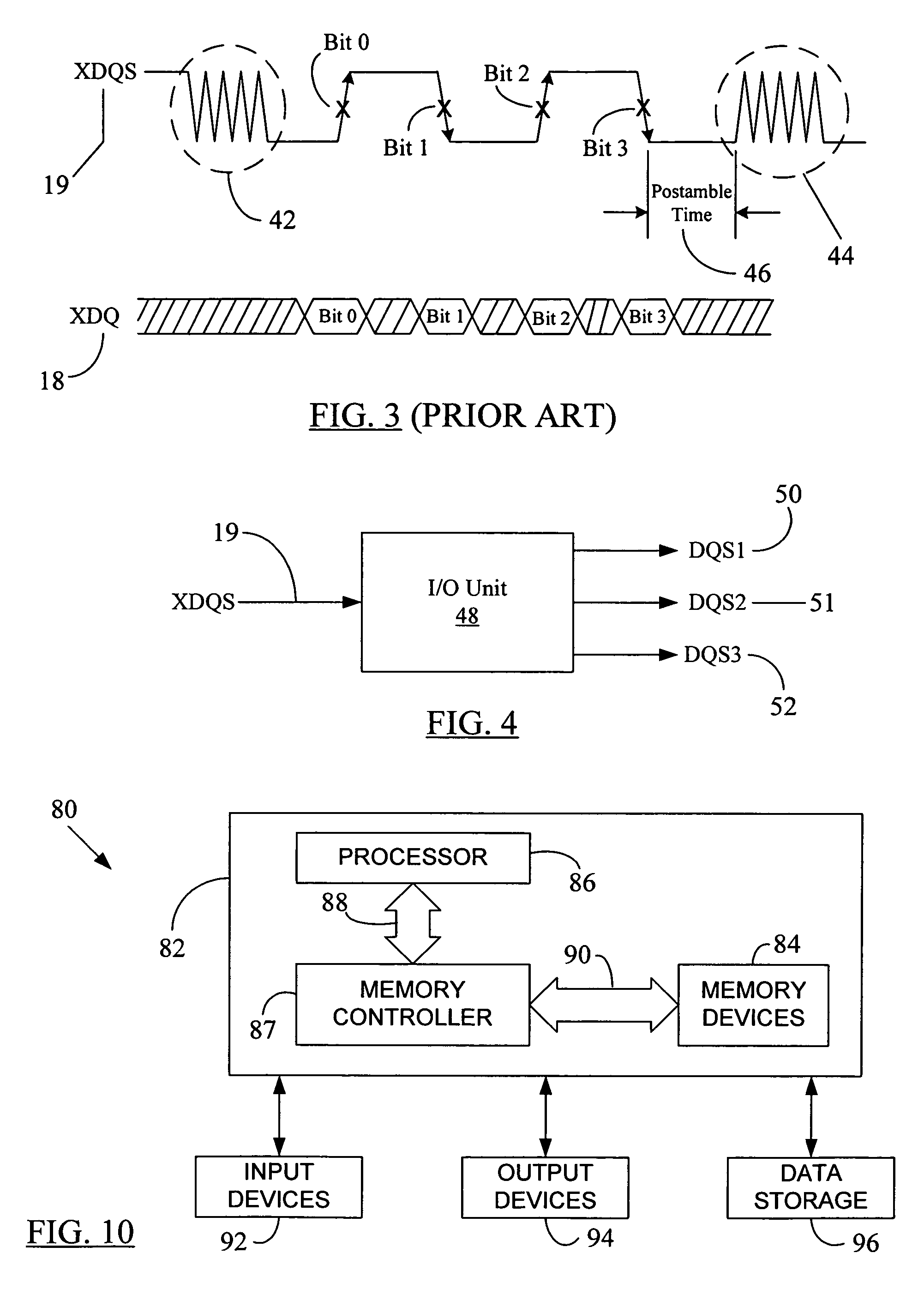
Therefore, any triggering of data flipflops by postamble ringing will result in incorrect data bits to be written into memory cells.
It is thus seen that the current buffer-based control of DQS postamble ringing may not be effective in itself, especially when modern memory chips are operated at ever faster clock speeds.
Thus, false data may not get “clocked in” or written into the memory chip because of postamble ringing.

Method used


Image

  • Solution to DQS postamble ringing problem in memory chips
  • Solution to DQS postamble ringing problem in memory chips
  • Solution to DQS postamble ringing problem in memory chips

Examples


Embodiment Construction

[0030]Reference will now be made in detail to some embodiments of the present disclosure, examples of which are illustrated in the accompanying drawings. It is to be understood that the figures and descriptions of the present disclosure included herein illustrate and describe elements that are of particular relevance to the present disclosure, while eliminating, for the sake of clarity, other elements found in typical solid-state electronic devices, memories or memory-based systems. It is noted at the outset that the terms “connected”, “connecting,”“electrically connected,” etc., are used interchangeably herein to generally refer to the condition of being electrically connected. It is further noted that various block diagrams and circuit diagrams shown and discussed herein employ logic circuits that implement positive logic, i.e., a high value on a signal is treated as a logic “1” whereas a low value is treated as a logic “0.” However, any of the circuit discussed herein may be easi...


PUM


Abstract

The disclosed system and method significantly reduce or eliminate DQS postamble ringing problem in modern high-speed memory chips, allowing the memory chips to be operated at significantly faster clock speeds. The external strobe signal (XDQS) may be used to generate at least two derivative strobe signals therefrom. Instead of the XDQS signal, the derivative strobe signals are then used, in a predetermined order, to clock in or strobe the data to be written into memory cells. The last generated derivative strobe signal may be used to finally transfer the data bits into memory cells. Once the last of the derivative strobe signals is activated, and so long as there are no more data writes pending in the command pipe for the next clock cycle, the rising or falling edge of the last derivative strobe signal can be detected to turn off further generation of the strobe signals prior to any onset of postamble ringing on the XDQS signal. Thus, false data may not get “clocked in” or written into the memory chip because of postamble ringing. This prevents data corruption and preserves the integrity of the data written into a memory chip.

Description

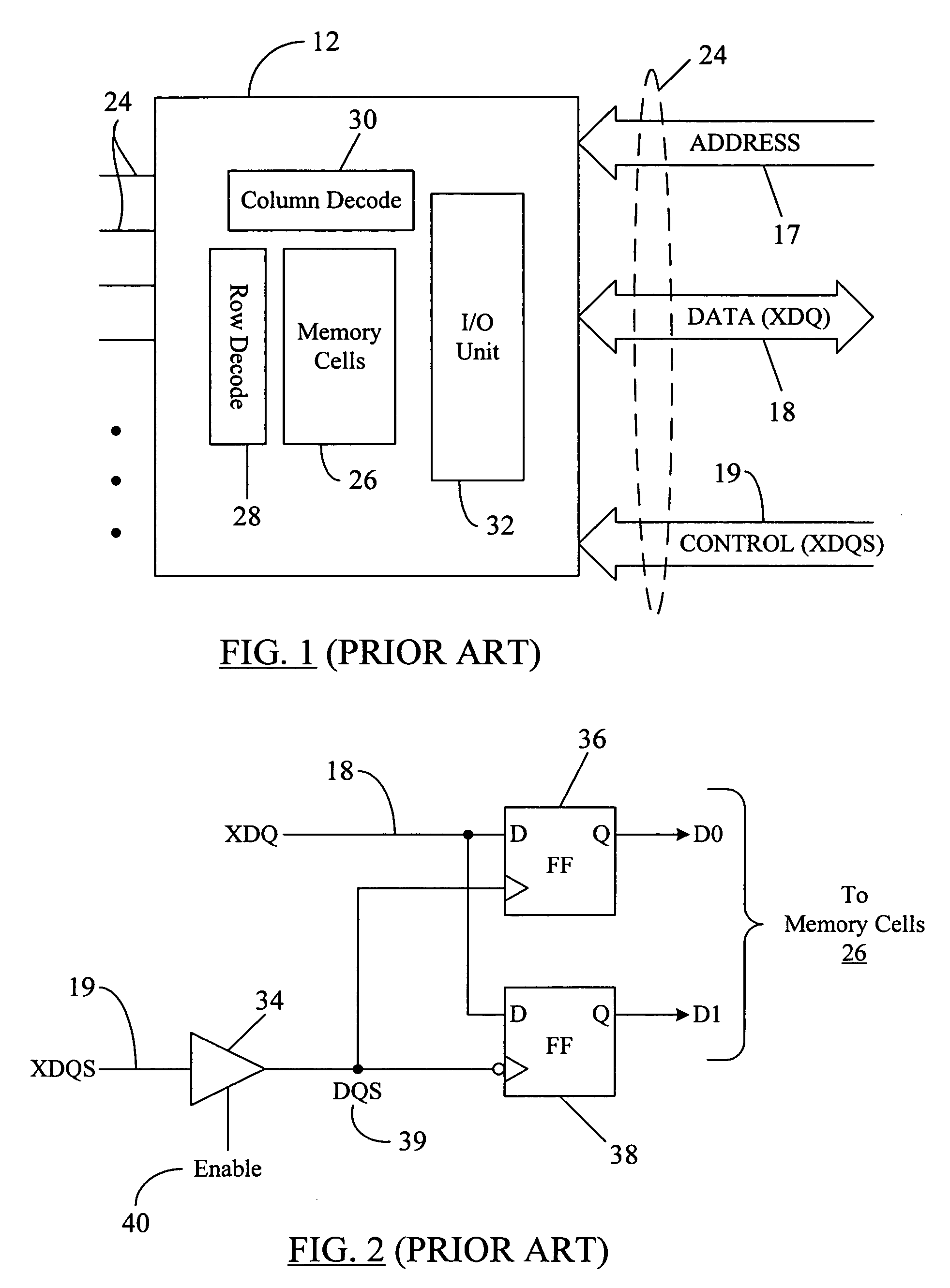
BACKGROUND[0001]1. Field of the Disclosure[0002]The present disclosure generally relates to memory devices and, more particularly, to a system and method to avoid DQS postamble ringing during memory writes.[0003]2. Brief Description of Related Art[0004]Memory devices are widely used in many electronic products and computers to store data. A memory device is a semiconductor electronic device that includes a number of memory cells, each cell storing one bit of data. The data stored in the memory cells can be read during a read operation. FIG. 1 is a simplified block diagram showing a memory chip or memory device 12. The memory chip 12 may be part of a DIMM (dual in-line memory module) or a PCB (printed circuit board) containing many such memory chips (not shown in FIG. 1). The memory chip 12 may include a plurality of pins 24 located outside of chip 12 for electrically connecting the chip 12 to other system devices. Some of those pins 24 may constitute memory address pins or address b...

Claims


Application Information

Patent Timeline
Patent Type & Authority Patents(United States)
IPC IPC(8): G11C7/00
CPCG11C7/1078G11C7/1087G11C7/222G11C7/22G11C7/1093
Inventor MUKHERJEE, SUGATOLI, WENMORZANO, CHRISTOPHER K.
Owner ROUND ROCK RES LLC
Why Eureka
Try Eureka