Frequency hopping data radio

a frequency hopping and data radio technology, applied in transmission, secret communication, electrical equipment, etc., can solve the problems of inability to operate at all when close to pagers or cell phone towers, frequency hopping systems are typically quite complicated and expensive to build, and the clocking mechanism is typically quite complicated. , to achieve the effect of low cost, high sensitivity and low power

Active Publication Date: 2006-09-05
DIGI INTERNATIONAL
View PDF6 Cites 19 Cited by
  • Summary
  • Abstract
  • Description
  • Claims
  • Application Information

AI Technical Summary

Benefits of technology

[0012]The present invention relates to radio frequency transmission systems. More particularly, the present invention relates to systems and methods that utilize a received signal to provide low cost, low power, high sensitivity, radio frequency hopping.
[0021]While the methods and processes of the present invention have proven to be particularly useful in the area of meter reading systems, those skilled in the art can appreciate that the methods and processes can be used in a variety of different applications to provide a system that includes a low cost, low power, high sensitivity, frequency hopping radio that enables communication.

Problems solved by technology

For example, because many technologies use the 900 MHz ISM band (e.g., cell phones, pagers, and cordless phones), existing 900 MHz radios are susceptible to interference and may not operate at all when close to pager or cell phone towers.
Frequency hopping systems, however, have their disadvantages as well.
This clocking mechanism is typically quite complicated and expensive to build.
Such indicators have the drawback that they don't reliably operate at the same sensitivity levels in which actual data receivers are capable of operating.
The problem with this type of encoding is that when several identical bits are sent in succession the receiver cannot inherently differentiate between when one bit stops and the next bit starts.

Method used


Image

  • Frequency hopping data radio
  • Frequency hopping data radio
  • Frequency hopping data radio

Examples


Embodiment Construction

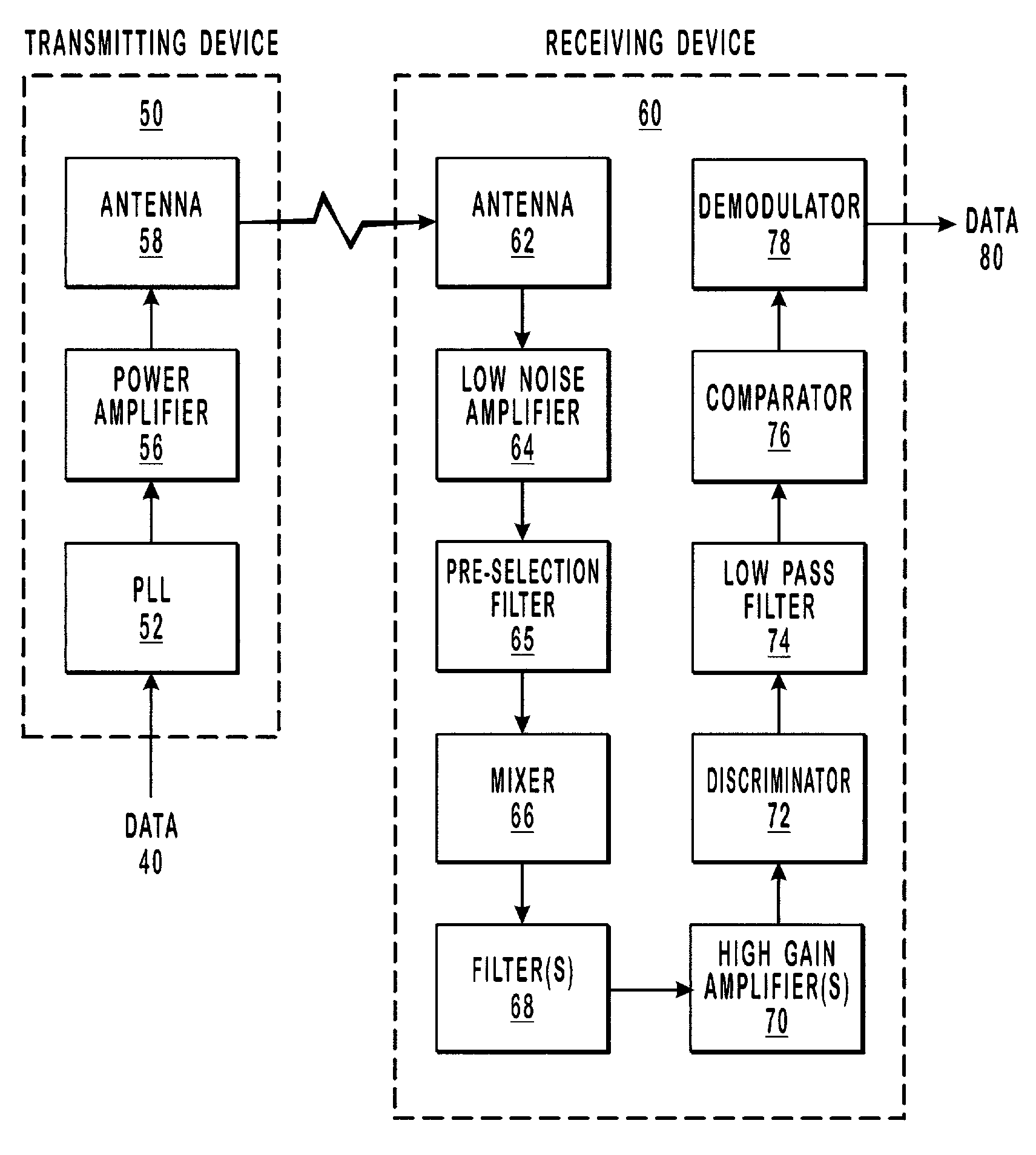
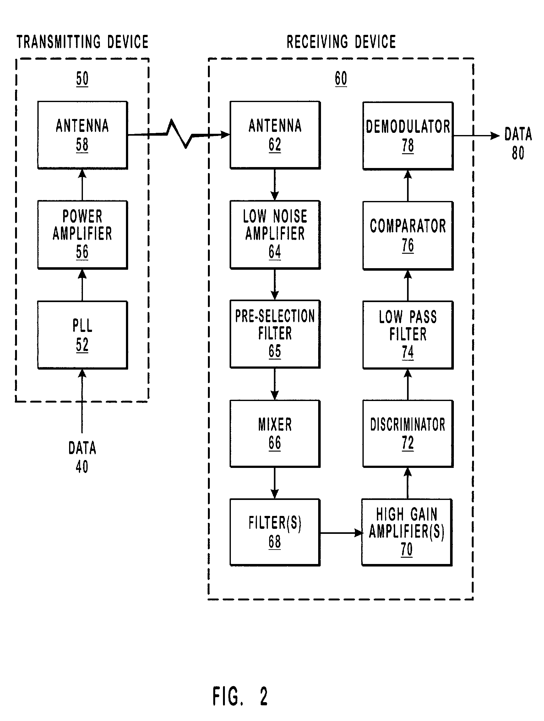
[0030]The present invention relates to radio frequency transmission systems. More particularly, the present invention relates to systems and methods that utilize a received signal to provide low cost, low power, high sensitivity, radio frequency hopping.

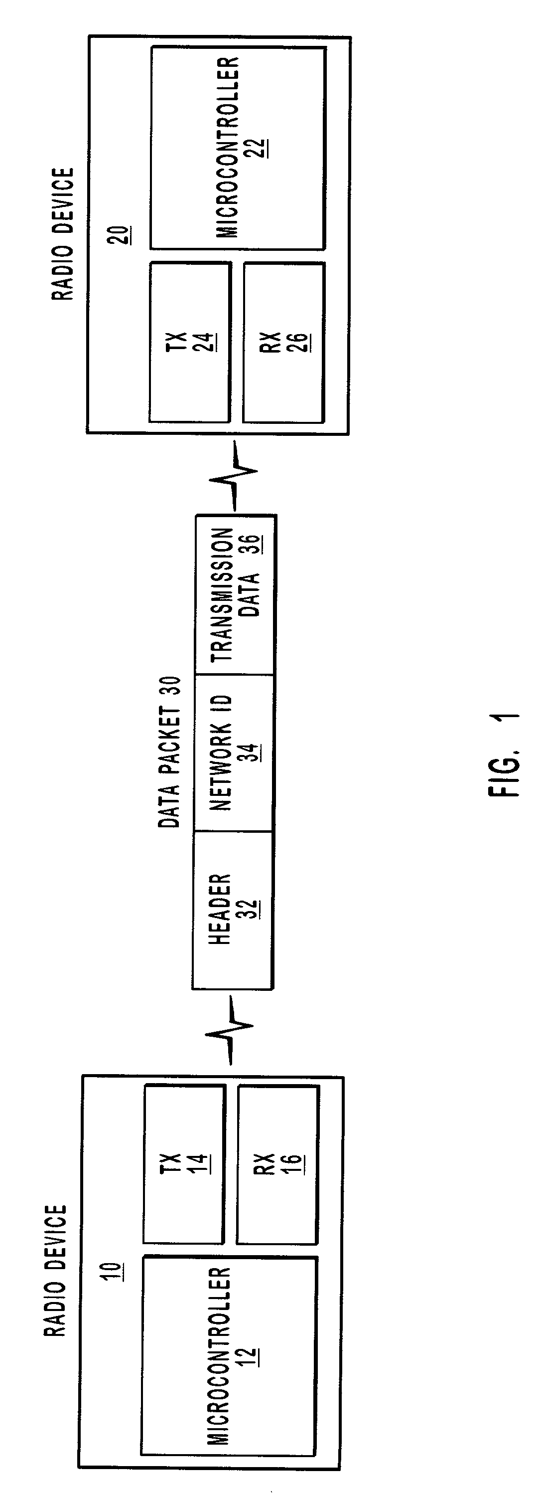
[0031]Embodiments of the present invention take place in association with an electronic system. In the disclosure and in the claims, the term “electronic system” shall refer to a computer device, computer system or other system, such as a supervisory control and data acquisition (SCADA) system, a remote meter reading system, a home automation system, an instrument monitoring system, or a point-of-sale (POS) system, that may be electronically coupled with a low power, high sensitivity, frequency hopping radio. The radio enables communication between two wireless points, where a cable, such as an RS232 cable, may have otherwise been used.

[0032]The following disclosure of the present invention is grouped into two subheadings, namely “Ra...


PUM


Abstract

Systems and methods that utilize a received signal to provide low cost, low power, high sensitivity radio frequency hopping communication. A transmitting system prepares a data packet that is to be communicated to a receiving system. The data packet includes a header, a network identification, and transmission data. A transmission frequency is identified and a phase lock loop (“PLL”) is set to the transmission frequency. The data packet is gathered, and frequency modulation and Differential Manchester encoding is performed. The signal is sent through a power amplifier and an antenna to a receiving system, which continually scans all channels of a frequency range for a valid signal. When a pulse is received, the signal is passed through a low noise amplifier, mixed down to 10.7 MHz, passed through one or more filters and one or more high gain amplifiers, mixed down to baseband, sent through a low pass filter, and then sent through a comparator. If an appropriate pulse width, expected bit pattern and a valid header are received, it is determined that the signal is valid and the entire data packet is demodulated to receive the transmitted data.

Description

BACKGROUND OF THE INVENTION[0001]1. Related Applications[0002]This application claims priority to U.S. Provisional Patent Application Ser. No. 60 / 236,844, filed Sep. 29, 2000, entitled “FREQUENCY HOPPING DATA RADIO.”[0003]2. Field of the Invention[0004]The present invention relates to radio frequency transmission systems. More particularly, the present invention relates to systems and methods that utilize a received signal to provide low cost, low power, high sensitivity, radio frequency hopping.[0005]3. Background and Related Art[0006]Wireless or radio frequency transmission is becoming increasingly more important in today's technology. Dispensing with the need for cables and complicated wiring, wireless technology enables networks to be connected quickly and easily. Several network-based applications may find wireless technology particularly advantageous, including supervisory control and data acquisition (SCADA), remote meter reading, home automation, instrument monitoring, point...

Claims


Application Information

Patent Timeline
Patent Type & Authority Patents(United States)
IPC IPC(8): H04B1/707H04B1/713H04K1/00
CPCH04B1/713
Inventor STEED, DAVIDNIELSEN, HUGH
Owner DIGI INTERNATIONAL
Why Eureka
Try Eureka