Material analysis using multiple X-ray reflectometry models

a reflectometry and material analysis technology, applied in the field of x-ray reflectometry, can solve the problems of long calculation time of fitting methods, limited results, and high non-linearity of error functions, so as to reduce calculation time, reduce the need for human involvement and expertise, and the effect of fast, automated analysis

Active Publication Date: 2006-09-05
BRUKER TECH LTD
View PDF27 Cites 19 Cited by
  • Summary
  • Abstract
  • Description
  • Claims
  • Application Information

AI Technical Summary

Benefits of technology

[0009]Embodiments of the present invention provide methods and systems for analyzing XRR measurements to find properties of a sample using a sequence of different model fitting methods. These embodiments are useful in reducing the calculation time needed for XRR analysis and minimizing the required human involvement and expertise. These features of the present invention thus enable fast, automated analysis, as required by applications such as production line testing in semiconductor fabs. In some semiconductor fab applications, the disclosed methods may be used to provide a real-time alert in case of process failure. This type of alert increases the overall yield of the process and avoids loss of material and the associated cost.
[0015]Furthermore, it is well known in the art that each model fitting method has characteristic advantages and limitations. Using the right combination of fitting methods in the correct order enables the advantages of each method to be exploited while avoiding its limitations. For example, genetic algorithms are typically slow to converge when operating over large parameter spaces, but are useful for optimizing the fit in a particular angular range when given an approximate model as initial condition. FFT-based methods, on the other hand, typically provide coarse precision but are useful for quick approximation of a model over a large parameter space. Levenberg-Marquardt and other gradient-based methods are useful for achieving a final high-precision fit given an approximate solution.
[0016]Using a sequence of two or more fitting methods also enables narrowing of the parameter space required for searching, thereby reducing the calculation time and increasing the probability of convergence to the correct solution. For example, sample thickness is measured by focusing on a particular angular range in the interference profile, referred to as the “oscillation range,” which shows a characteristic pattern of periodic oscillations. The angular frequency of these oscillations is inversely proportional to the thickness of the sample or one of its layers. A sequence of fitting methods may begin with identifying the relevant oscillation range using an FFT-based method, then performing a GA fit only within the oscillation range.
[0017]Some embodiments of the present invention also use different FOMs (Figures-Of-Merit) in the fitting process for quantifying the agreement between the simulated interference profile and the measured XRR spectrum. Using different FOMs in a single fitting sequence provides a better ability to extract information regarding different material layers and helps to avoid false local minima, as will be explained below.
[0028]In still another embodiment, applying the multi-step analysis includes reducing a volume of data in the X-ray spectrum so as to generate a compressed spectrum, and then fitting the simulated model to the compressed spectrum.

Problems solved by technology

Several limitations may be encountered when using individually any one of the model fitting methods described above:1. Long calculation time: Some of the fitting methods require a long calculation time in order to converge to a solution.
However, the error function is typically a highly non-linear function and in many practical cases comprises local minima in addition to the global minimum that reflects the true solution to the fitting problem.
Some of the currently-available fitting methods are prone to convergence to false local minima.
This residual error may be due to a large iteration step-size or other resolution limitation.4. Limited parameter range: Some currently-available fitting methods may operate only over a limited range of measured parameters.

Method used


Image

  • Material analysis using multiple X-ray reflectometry models
  • Material analysis using multiple X-ray reflectometry models
  • Material analysis using multiple X-ray reflectometry models

Examples


Embodiment Construction

XRR System Description

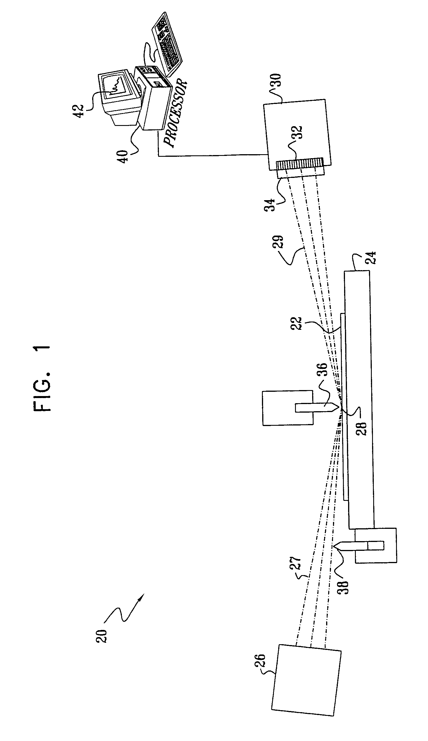
[0083]FIG. 1 is a schematic illustration of a system 20 for X-ray reflectometry (XRR) of a sample 22, in accordance with an embodiment of the present invention. The sample is typically mounted on a motion stage 24, allowing accurate adjustment of its position and orientation. An X-ray source 26 irradiates a small area 28 on sample 22. A dynamic knife edge 36 and a shutter 38 may be used to limit an incident beam 27 of the X-rays, as described in the above-mentioned U.S. Pat. No. 6,512,814.

[0084]A reflected beam 29 of X-rays from sample 22 is collected by a detector assembly 30. Typically, assembly 30 collects reflected X-rays over a range of reflection angles between about 0° and 5°, both below and above the critical angle of the sample for total external reflection. Assembly 30 comprises a detector array 32, typically arranged in either a linear or a matrix (two-dimensional) array.

[0085]A reflectometry processor 40 analyzes the output of assembly 30, so as to ...


PUM


Abstract

A method for inspection of a sample includes irradiating the sample with a beam of X-rays, measuring a distribution of the X-rays that are emitted from the sample responsively to the beam, thereby generating an X-ray spectrum, and applying a multi-step analysis to the spectrum so as to determine one or more physical properties of a simulated model of the sample. The multi-step analysis includes spectrally analyzing the spectrum so as to determine one or more characteristic frequencies and fitting the simulated model to the spectrum by an iterative optimization process beginning from an initial condition determined by the one or more characteristic frequencies.

Description

FIELD OF THE INVENTION[0001]The present invention relates generally to X-ray reflectometry, and specifically to methods and systems for thin film analysis using X-rays.BACKGROUND OF THE INVENTION[0002]X-ray reflectometry (XRR) is a well-known technique for measuring the thickness, density and surface quality of thin film layers deposited on a substrate. X-ray reflectometers typically operate by irradiating a sample with a beam of X-rays at grazing incidence, i.e., at a small angle relative to the surface of the sample, near the total external reflection angle of the sample material. Measurement of X-ray intensity reflected from the sample as a function of angle gives a profile of interference fringes, which is analyzed to determine the properties of the film layers responsible for creating the fringe profile. Several X-ray reflectometers have been described in the patent literature, such as U.S. Pat. Nos. 6,512,814, 5,619,548 and 5,923,720, whose disclosures are incorporated herein ...

Claims


Application Information

Patent Timeline
Patent Type & Authority Patents(United States)
IPC IPC(8): G01T1/36
CPCG01N23/20
Inventor AGNIHOTRI, DILEEPDIKOPOLTSEV, ALEXYOKHIN, BORIS
Owner BRUKER TECH LTD
Why Eureka
Try Eureka