Adaptive feedback channel for radio frequency power amplifiers

a radio frequency power amplifier and feedback channel technology, applied in the field of radio frequency power amplifiers, can solve the problems of limited dynamic control range, inability to meet present and future rf system requirements, and lack of dynamic output level control, efficiency and linearity, to achieve the effect of improving amplifier stability and higher system gain

Active Publication Date: 2006-09-05
ROCKWELL COLLINS INC
View PDF1 Cites 59 Cited by
  • Summary
  • Abstract
  • Description
  • Claims
  • Application Information

AI Technical Summary

Benefits of technology

[0005]A radio frequency (RF) amplifier system includes an RF power amplifier having an input and an output, and a typical gain of about 1000 between the input and the output. Amplifier stability is improved with higher system gain. An adaptive feedback channel is coupled between the input and the output of the RF power amplifier. The adaptive feedback channel receives as inputs audio signals for AM modulation of the input of the RF power amplifier, a frequency command word indicative of a desired frequency

Problems solved by technology

Contemporary radio frequency (RF) power amplifiers lack the dynamic output level control, efficiency, and linearity to meet present and future RF system requirements.
These current designs have limited dynamic control range and less than desired output level stability in applications such as amplitude modulation (AM), frequency modulation (FM), spread spectrum, and special modulation waveform signals.
Shifting the “Q” point degrades amplifier efficiency and linearity.
This degradation is not acceptable in many systems.
Applying the same operational amplifier feedback theory to RF power amplifiers has not been practical because the basic operational amplifier

Method used


Image

  • Adaptive feedback channel for radio frequency power amplifiers
  • Adaptive feedback channel for radio frequency power amplifiers
  • Adaptive feedback channel for radio frequency power amplifiers

Examples


Embodiment Construction

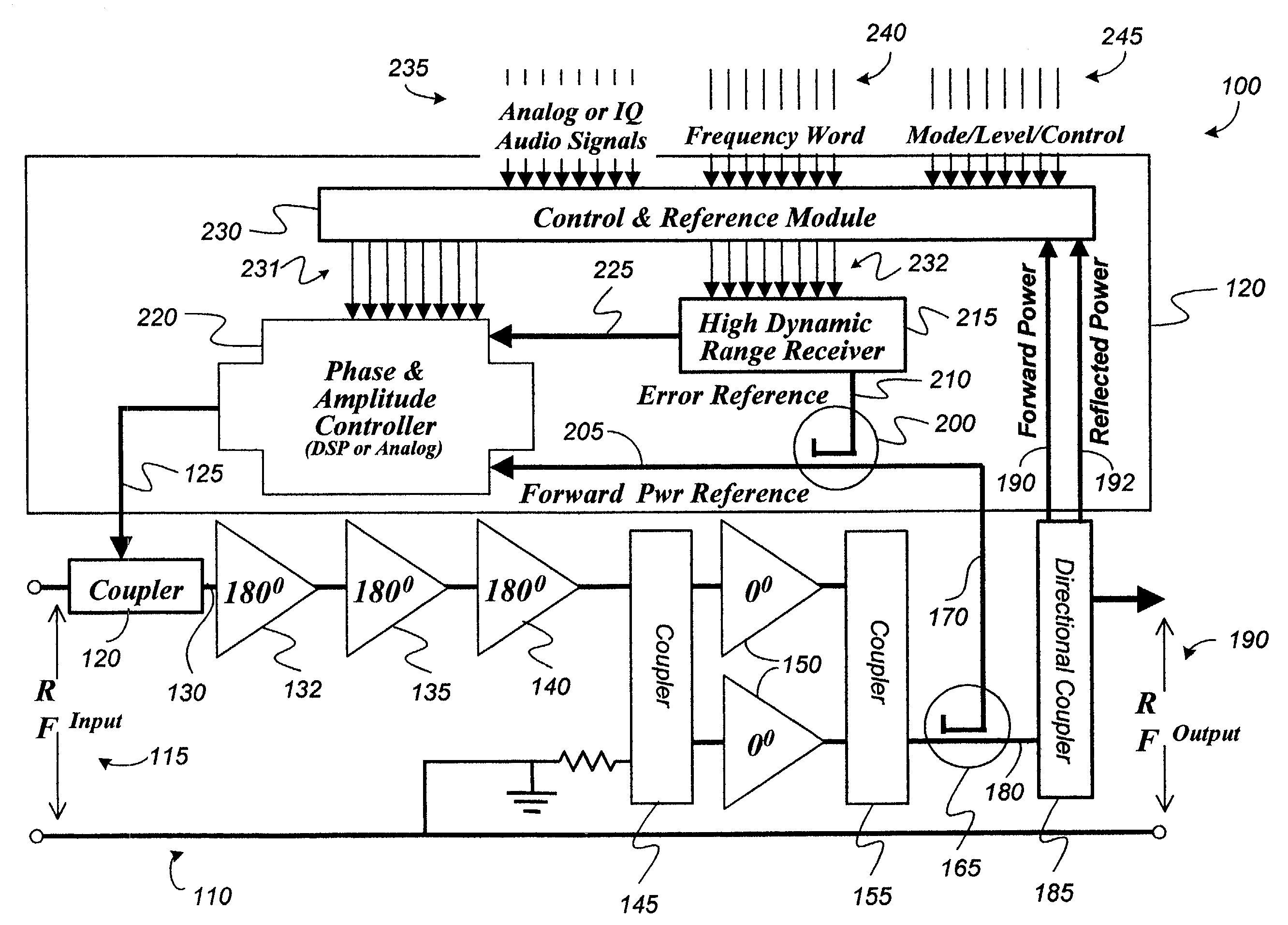
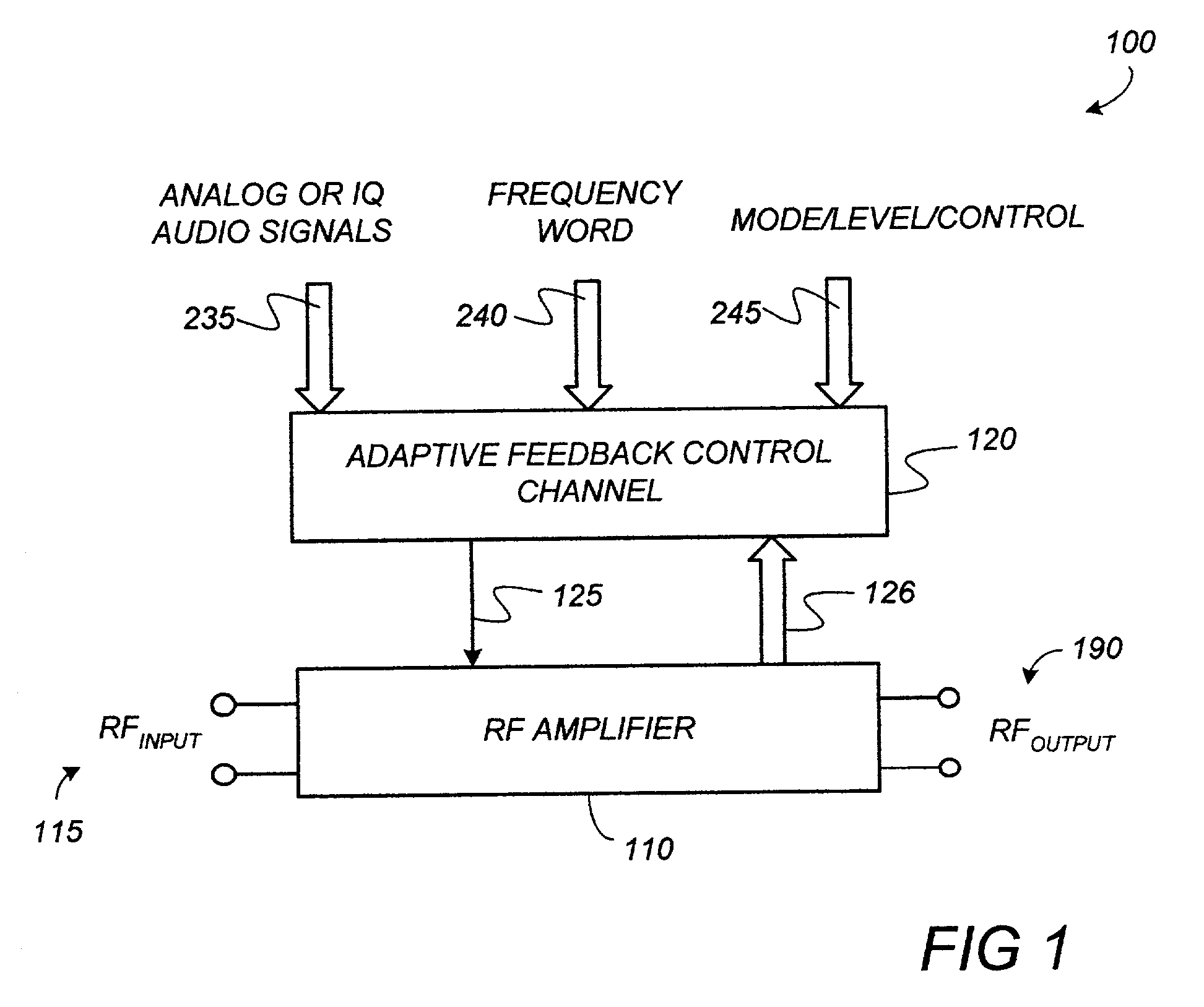
[0008]FIG. 1 is a block diagram which illustrates a feedback controlled RF power amplifier 100 in accordance with the present invention. RF power amplifier 100 includes an amplifier circuit 110 and an adaptive feedback control channel 120. Amplifier circuit 110 is an RF amplifier circuit having high gain, for example having a typical gain of 1,000 or greater, for amplification of an RF input signal RFinput 115. While gains as low as 30 can be used with the adaptive feedback control channel of the invention, higher gains of at least between 100 and 1000 will provide improved stability and performance. Generally, however, the adaptive feedback control channel concepts disclosed herein are gain independent.

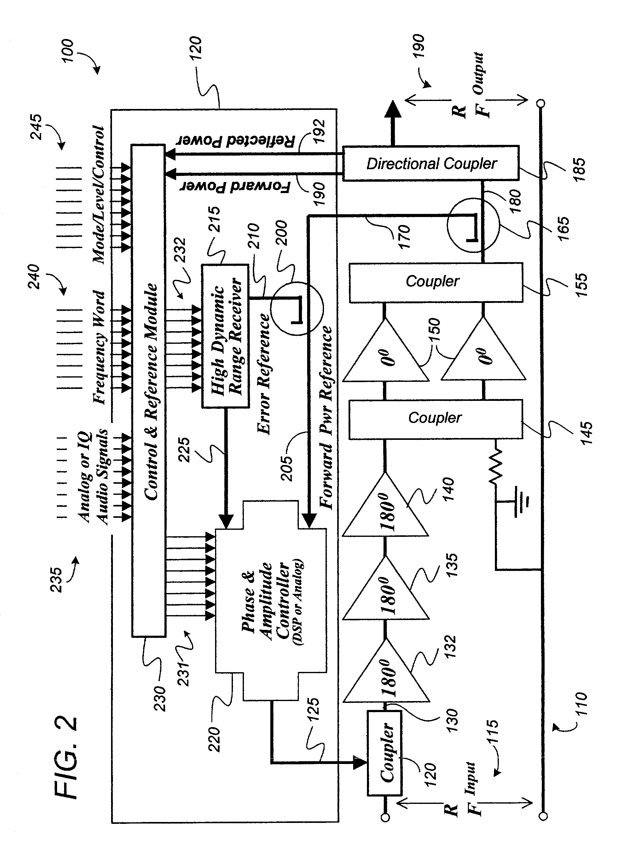
[0009]Using adaptive feedback control channel 120, dynamic output level control, efficiency and linearity of amplifier circuit 110 are enhanced. FIG. 2 is a block diagram illustrating a more particular embodiment of RF power amplifier 100. FIGS. 1 and 2 are discussed together to bett...


PUM


Abstract

A radio frequency (RF) amplifier system includes an RF power amplifier having an input and an output, and a typical gain of 1000 or more between the input and the output. An adaptive feedback channel is coupled between the input and the output of the RF power amplifier. The adaptive feedback channel receives as inputs audio signals for modulation of the input of the RF power amplifier, a frequency command word indicative of a desired frequency and phase of the RF amplifier system, and a control word indicative of a desired power level of the output of the RF power amplifier and of a mode of operation of the RF amplifier system. In response to the inputs, the adaptive feedback channel provides as an output a degenerative feedback signal to the input of the RF power amplifier.

Description

FIELD OF THE INVENTION[0001]The present invention relates to radio frequency power amplifiers. More particularly, the present invention relates to feedback for radio frequency power amplifiers which enhances the dynamic output level control, efficiency and linearity of the radio frequency power amplifier.BACKGROUND OF THE INVENTION[0002]Contemporary radio frequency (RF) power amplifiers lack the dynamic output level control, efficiency, and linearity to meet present and future RF system requirements. Present technology RF power amplifiers utilize an analog Automatic Level Control (ALC) to control RF power output levels. These current designs have limited dynamic control range and less than desired output level stability in applications such as amplitude modulation (AM), frequency modulation (FM), spread spectrum, and special modulation waveform signals. One prior art RF power amplifier control methodology is to shift the active element's bias or operational “Q” point, which changes ...

Claims


Application Information

Patent Timeline
IPC IPC(8): H01Q11/12
CPCH03C5/00H03F1/02H03F1/0205H03F1/32H03F1/3247H03F1/3282H03F3/24H03F3/19H03F2201/3206H03F2200/132H03F2200/198H03F2200/204H03F2200/207H03F2200/372
Inventor THON, ROBERT J.
Owner ROCKWELL COLLINS INC
Why Eureka
Try Eureka