Image processing apparatus, output apparatus, image processing system and image processing method

Inactive Publication Date: 2006-09-05
FUJIFILM BUSINESS INNOVATION CORP
View PDF18 Cites 27 Cited by
  • Summary
  • Abstract
  • Description
  • Claims
  • Application Information

AI Technical Summary

Benefits of technology

[0009]In view of the foregoing, an object of the present invention is to provide an image processing system wh

Problems solved by technology

However, the image processing system, which has the structure that the host-side apparatus generates PDL data and the output apparatus generates intermediate format data so that the banding process is performed, cannot reduce the load which must be borne by the output apparatus.
Therefore, there arises a problem in that long waiting time is required until a printing process is completed if a plurality of host apparatuses simultaneously make demands to perform printing operations.
Another problem arises in that a memory must be provided which temporarily stores image data in order to perform the compressing process.
The system structured to cause the

Method used


Image

  • Image processing apparatus, output apparatus, image processing system and image processing method
  • Image processing apparatus, output apparatus, image processing system and image processing method
  • Image processing apparatus, output apparatus, image processing system and image processing method

Examples


Example

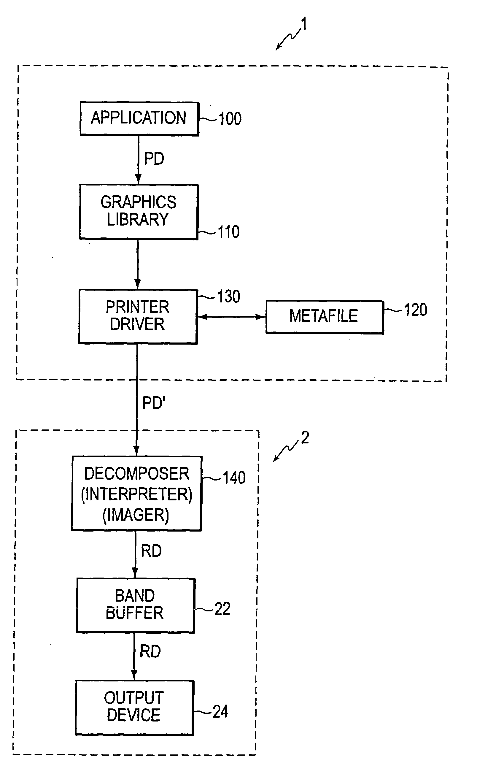
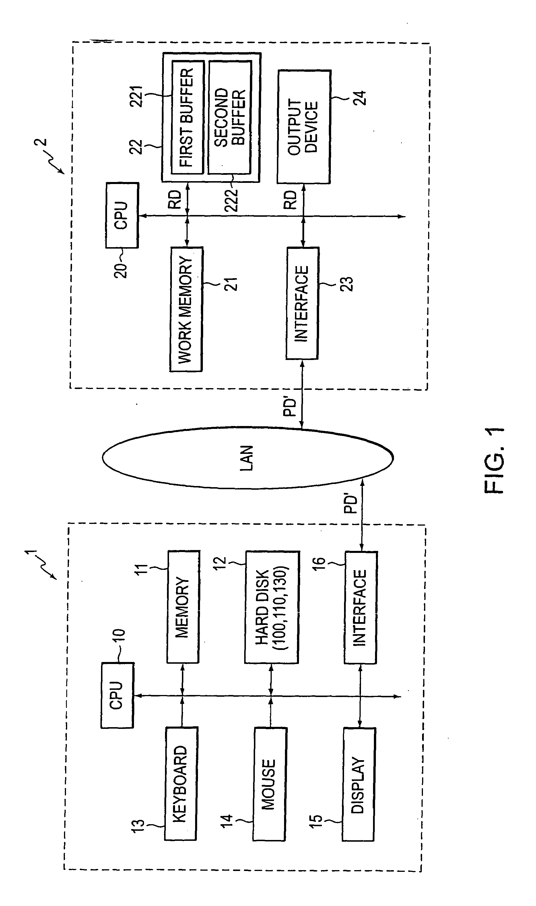
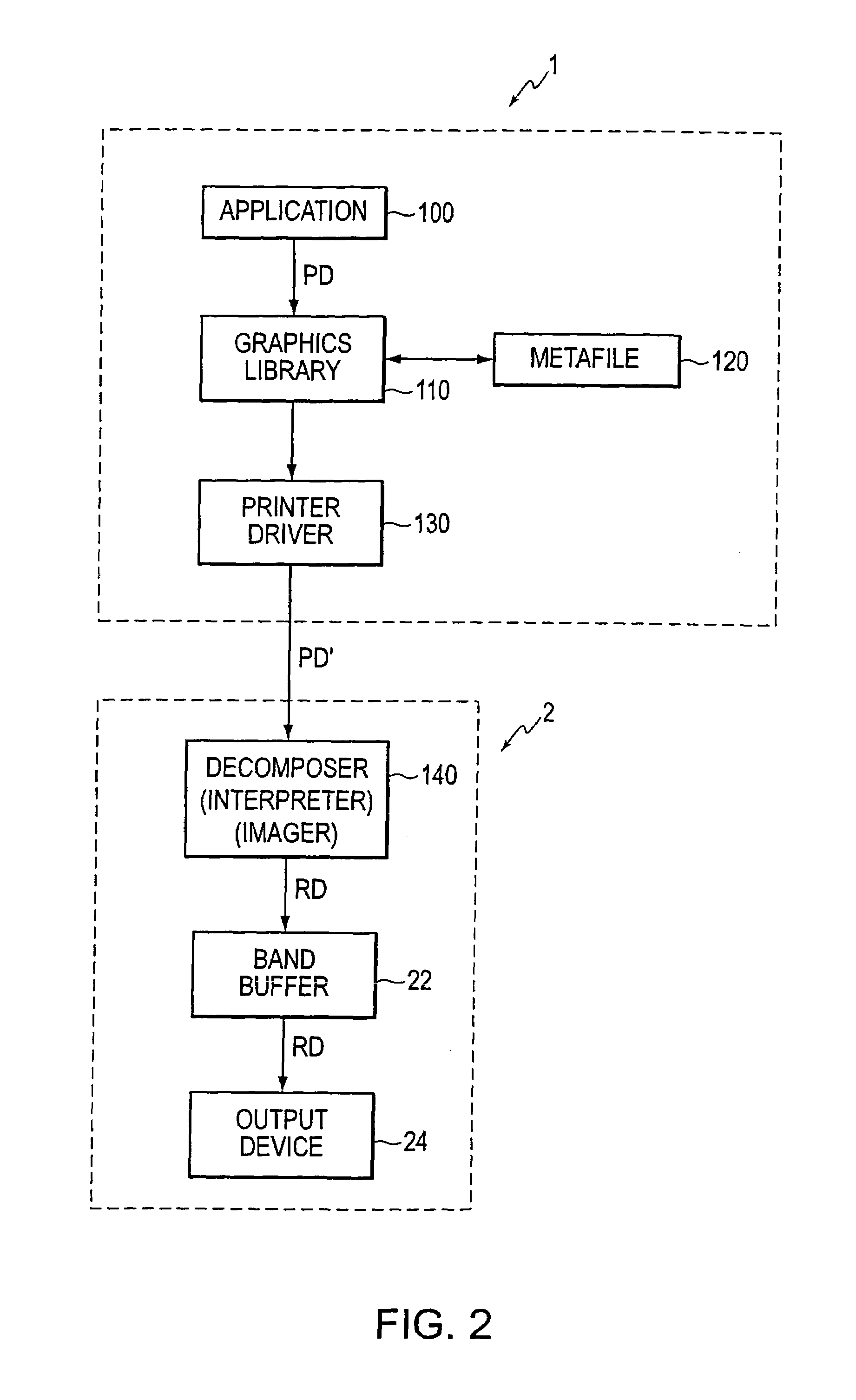
[0030]The overall structure of an image processing system according to a first embodiment of the present invention will now be described. FIG. 1 is a block diagram showing the image processing system according to this embodiment. As shown in the drawing, the image processing system incorporates a host computer 1, an output apparatus 2 and local area network LAN.

[0031]The host computer 1 incorporates a CPU (Central Processing Unit) 10 for controlling the elements of the host-side apparatus, a memory 11 serving as a working memory for the CPU 10, a hard disk 12 for storing large-capacity data and various programs, a keyboard 13 and a mouse 14 serving as input devices, a display unit 15 for displaying an image and an interface 16 for establishing the communication with the local area network LAN.

[0032]In the hard disk 12, there are stored a variety of applications 100 for use in the image process and a printing program for printing print data PD generated by the foregoing applications....

Example

Second Embodiment

[0052]The image processing system according to the first embodiment has the structure that print data PD generated by the applications 100 is temporarily stored in the metafile 120 by the graphics library 110. After print data PD for one page has been stored, the graphics library 110 extracts, from the metafile 120, objects which constitute the bands which must be processed. As a result, print data PD reconstructed in band units is generated, and then print data PD is transmitted to the printer driver 130. The foregoing embodiment is structured such that the banding process for reconstructing print data PD for one page in band units is performed by the graphics library 110. Since the applications 100 and the graphics library 110 perform the process in cooperation with each other, the applications 100 are freed up after the banding process which is performed by the graphics library 110 has been completed. Therefore, if the data quantity of print data PD is large, lon...

Example

Third Embodiment

[0056]The image processing system according to the second embodiment has the structure that the graphics library 110 transfers print data PD to the printer driver 130 after the applications 100 have generated print data PD. The graphics library 110 temporarily stores print data PD in the metafile 120. Then, objects which must be drawn in the bands which must be processed are extracted from the metafile 120. Thus, print data PD reconstructed in band units is generated.

[0057]The banding process structured as described above is able to as it is process extracted print data PD if one object is included in a certain band. If one object is placed across a plurality of bands, a drawing command relating to the same objects in each band is generated when the conversion to PDL data PD′ is performed. If objects are expressed by an image, such as a photograph, and the object is placed across a plurality of bands, image data allowed to overflow the band is wasted. Thus, the effic...


PUM


Abstract

When print data PD generated by applications 100 is supplied to a graphics library 110 in an order of describing objects, the graphics library 110 makes correspond print data PD to objects so as to store print data PD in a metafile 120. After print data for one page has been stored in the metafile 120, the metafile 120 is retrieved. Thus, print data PD is reconstructed for each band. A printer driver 130 converts reconstructed print data PD into the PDL data PD′ so as to transfer the PDL data PD′ to an output apparatus 2. A decomposer 140 does not generate intermediate format data and directly develops the PDL data PD′ in a band buffer 22. An output device 24 reads raster data RD from the band buffer 22 so as to print an image on a paper sheet.

Description

BACKGROUND OF THE INVENTION[0001]The present invention relates to an image processing apparatus, an output apparatus, an image processing system and an image processing method arranged to perform a banding process such that a process for dividing objects across bands is performed so that an image is directly drawn on a band buffer without a necessity of generating an intermediate language.[0002]An output apparatus for interpreting print data supplied from a host side application to produces an output of an image on a printing sheet or the like generally incorporates a work memory required to convert print data into a raster scan type format and a memory to serve as an output buffer for storing converted raster data. In particular, the output buffer must have a large memory capacity because raster data obtained by raster development must be stored. Therefore, a major portion of the output apparatuses is structured to perform a process for dividing one page in a sub-scanning direction...

Claims


Application Information

Patent Timeline
IPC IPC(8): G06F15/00B41J5/30G06F3/12
CPCG06F3/1204G06F3/1288G06F3/123
Inventor SANO, MAKOTOMIYAZAKI, MASAYA
Owner FUJIFILM BUSINESS INNOVATION CORP
Why Eureka
Try Eureka